Introduction to UML (Part 1)
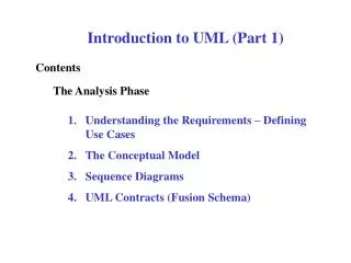
Introduction to UML (Part 1). Contents. The Analysis Phase. Understanding the Requirements – Defining Use Cases The Conceptual Model Sequence Diagrams UML Contracts (Fusion Schema). defined on next slide. Requirements Analysis.

Introduction to UML (Part 1)
E N D
Presentation Transcript
Introduction to UML (Part 1) Contents The Analysis Phase • Understanding the Requirements – Defining Use Cases • The Conceptual Model • Sequence Diagrams • UML Contracts (Fusion Schema)
defined on next slide Requirements Analysis Use Cases – A narrative describing the sequence of events of an actor (external agent) using a system to complete a process. Example – Making a Withdrawl from an ATM Machine Use case: Withdrawl Actors: Customer Type: primary* Description: A customerarrives at an ATM machine, inserts her Debit Card into the machine, enters her passcode when prompted to do so, selects the Withdrawl option from the menuof choicespresented, enters the amount in increments of the appropriate denominations, and if the amount specified is less than or equal to the limit allowed and less than her current balance, billsare dispensed, the amountdeductedfrom her account, and her Cardreturned.
Requirements Analysis In the use case example on the previous page, noun phrases have been underlined, and verb phrases, written in italics. Use cases are vehicles for identifying the concepts in the problem domain and the associations between these concepts. • The Type field in the previous example may be either: • primary – use case represents major or common process. • secondary – use case represents a minor or rare process. • optional – use case represents a “frill” that may not be implemented
Requirements Analysis Use cases and Functional Requirements • End users have goals that they want the system to help meet • Use cases capture these goals and describe the functional requirements of the system needed to meet these goals • A scenario is a specific sequence of actions and interactions between actors and the system being modeled • A use case is a collection of related success and failure scenarios that describe the actions of the system to support a goal.
Parentheses here are used to denote optional Requirements Analysis “Fully Dressed” Use Case template Use Case name (and number) The goal being described Primary Actor Captures behaviors related to each stakeholder’s interests Stakeholders and Interests Preconditions Statements that must be true before and after the successful completion of the goal Post-conditions Main Success Scenario Records all interactions between actors, and validations of actions and changes of state by the system Extensions or Alternate Flows Additional references to constructing use cases
Requirements Analysis In specifying the requirements for the system to be built, the analyst must identify the boundaries of the system, the Actors (or outside agents) that will interact with the system, and the high level use cases that outline the processes that the system will be called upon to perform. In the example illustrated on the next slide, this process of identifying the system boundary along with the actors that interact with the system, and the complete set of high level use cases for this system, is depicted diagrammatically for a Point of Sales Terminal (POST) System.
Add high level use cases Indicate Actors for each use case Actors Log in Buy Items Refund Purchased items Requirements Analysis System Boundaries System to be built POST Customer Cashier
System Analysis – Building the Conceptual Model Terminology • Concept – Idea, thing, or object in the the problem domain • Class – Realization of a concept in the design and implementation of the system. • Attribute – Descriptive characteristic of a concept • Association – An ongoing relationship between concepts.
System Analysis – Building the Conceptual Model In constructing an object-based system, one must begin by: • Identifying the objects (classes) that collaborate to produce the required functionality of the system. Start by identifying the Concepts in the problem domain • Identifying the long-term associations between classes of objects that have to be “remembered”; To what kind of objects do members of each class send messages? • Identifying the data that each object must hold; These are the attributes of each Concept in the problem domain • Identifying the messages to which an object must be able to respond, who they are sent by, and what behaviors an object is required to exhibit. Adding behaviors (and the algorithms for implementing them) is a major focus of the design process
Class name or label Name attributes primitive data members object data members references to other objects Integers, reals, Strings, etc. Bound objects opaque to the rest of the system Independent objects that receive messages from this Behaviors of the object (needed to respond to messages it receives) – includes method name, parameter list, and return type methods Systems Analysis – Building the Conceptual Model Structure of a Class (The progressive refinement of a Concept)
System Analysis – Building the Conceptual Model Step 1 – Identify concepts from the use cases If it exists in the problem domain and is not a number or text, it’s a concept. Example – Consider the Withdrawl use case previously shown Candidates Noun phraseDecision Customer Concept (Actor) ATM Machine Concept Debit Card Concept passcode Concept Menu of options Concept Withdrawl option Attribute of Menu Amount Attribute (of Transaction) Increments …. Constraint Limit allowed Concept Account Concept Current Balance Attribute of Account Bill (Currency denomination) Concept
Account Name of Concept ID_num: String owner: String balance: double Attributes System Analysis – Building the Conceptual Model Step 2 – For each concept identified, draw a rectangular box In the first Conceptual Model it is not necessary (nor necessarily desirable) that all of the attributes and their types be listed. You should limit yourself to just those attributes appearing in the use cases, and you should not list the types. (It is an implementation detail left for the Class Model Diagram.)
Account Customer A customer may have multiple bank accounts as indicated by the multiplicity star (* = 0 or more) An Account may have a multiplicity of 1 or 2 (joint) owners System Analysis – Building the Conceptual Model Step 3 – Adding associations Associations can be discovered from the verb phrases in the use cases. 1..2 * owns An association has a label reading from left to right (or from top to bottom)
* 1 contains Product Specification Product Catalog description 1 price UPC used_by * 1 describes * Store 1 stocks * Item name address serial # System Analysis – Building the Conceptual Model Distinguish between the physical object and the specification of that object when: deleting the physical object leads to loss of information that needs to be maintained
System Analysis – Building the Conceptual Model During the design phase, we will convert the conceptual model into the Class Diagram (also called the Object Model Diagram). At that time we will not only add classes from the solution domain (the domain of the software implementation), but we will also add additional refinements to the description of the associations
System Analysis – Sequence Diagrams Sequence diagrams illustrate the operations that Actors request of a system (system Operations) and the external events (if any) that the system produces as a result of each operation. Computer systems do not initiate events – they can only respond to requests or stimuli from agents outside the system boundary. Each system operation will initiate changes in the state of the system that may be accompanied by an output (external event). It is the job of the analyst to establish the pattern of collaboration between the objects in the system needed to perform each system operation.
System Customer Cashier enteritem(UPC,quantity) endSale() presentCard(CreditCard) recordPayment(amount) System Analysis – Sequence Diagrams while items do if accepted Example taken from the use case Buy Items
System Analysis – Sequence Diagrams To construct a sequence diagram for a typical sequence of events for a use case: • Draw a vertical line representing the system as a black box. (We are only concerned with the “stimuli” and response of the system – not its internal details.) Time increases in the direction of the line from top to bottom. • Draw a line for each Actor identified in the use case. • Identify the system Operations that each Actor generates, and indicate them as directed horizontal line segments arranged in sequence on the diagram. • Indicate with textual notes those operations that occur conditionally or repeatedly.
System Analysis -- Contracts For each System Operation a Contract will indicate Name: Name of the system Operation Description: Brief narrative Collaborating Objects (Classes) Creates: Classes of objects created Changes: Classes of objects whose state is changed Reads: Classes of objects read, not altered Output: Value or object returned Preconditions: States that will not raise an exception Exception: Action taken if preconditions not met\ Post-conditions: State of system after completion
System Analysis -- Contracts To make a Contract (Schema) for each use case: • Identify system operations from the sequence diagrams • For each system operation, construct a contract • Start by writing the Description, informally describing the purpose of the operation (in terms of the concepts previously defined) • List the preconditions that must be true for this operation to be successfully completed • Describe the post-conditions, listing objects created or dissolved, attributes modified, associations formed or broken • From the description and the post-conditions, determine which (classes of) objects are created, changed, or read during the implementation of the operation.
System Analysis -- Contracts Example: Consider a system operation in the ATM example – processWithdrawl(amount: double) Description: If the amount indicated is less than the balance in the customer’s account, is less than or equal to the transaction limit, and is divisible by the minimum denomination, then a transaction occurs in which the customer’s account balance is reduced by the amount of the transaction, the transaction is recorded by the bank, and the customer is issued money and a receipt.
System Analysis -- Contracts Precondition: The amount of the transaction is less than the customer’s account balance, AND the amount is less than or equal to the transaction limit, AND the amount is divisible by the minimum denomination Exception: The failed transaction is recorded by the bank and no money is dispersed to the customer. The transaction is dissolved and a new menu is presented.
State transition Attribute Modification Association formed or broken Instances of creation/deletion of objects System Analysis -- Contracts Post-conditions: Transaction is completed Account.balance changed Transaction.data added to BankRecord StartMenu is displayed Account association is discontinued
System Analysis -- Contracts Changes: Account.balance Transaction.data BankRecord Menu Reads: Account.balance Transaction_limit Min_denomination Creates/Dissolves: Transaction Output: Bills – to Customer
Analysis Phase This concludes the formal analysis stage. As you proceed with the design, concepts will become more clearly delineated, omissions will be recognized, and you will undoubtedly return and refine your analysis models. Realize that the whole purpose of this exercise is to improve your design and facilitate the implementation and maintenance of your system. The analysis and design is not an end in itself, but a precursor to the construction of a robust and useful system. Building a significant software system with inadequate analysis and design is analogous to constructing a major building without appropriate blueprints and architectural models. Every step in the analysis and design should ultimately translate to the implementation details, or else it is an inherently useless exercise.
Postscript I met a traveller from an antique land Who said: Two vast and trunkless legs of stone Stand in the desert … Near them, on the sand, Half sunk, a shattered visage lies, whose frown, And wrinkled lip, and sneer of cold command, Tell that its sculptor well those passions read Which yet survive, stamped on these lifeless things, The hand that mocked them, and the heart that fed: And on the pedestal these words appear: ‘My name is Ozymandias, king of kings: Look on my works, ye mighty and despair!’ Nothing beside remains. Round the decay Of that colossal wreck, boundless and bare The lone and level sands stretch far away. Percy Bysshe Shelly 1818