1 / 0

2005 Pioneer Home Audio Seminar

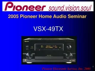
2005 Pioneer Home Audio Seminar. VSX49TX. Pioneer Electronic Service, Inc. 2005. Welcome one and all! Your instructor…Dave Kraus. Introduction. Why the VSX49TX? The VSX49TX is not current product, however it tends to be the most difficult to repair! What will be covered?

trish
Télécharger la présentation

2005 Pioneer Home Audio Seminar

An Image/Link below is provided (as is) to download presentation Download Policy: Content on the Website is provided to you AS IS for your information and personal use and may not be sold / licensed / shared on other websites without getting consent from its author. Content is provided to you AS IS for your information and personal use only. Download presentation by click this link. While downloading, if for some reason you are not able to download a presentation, the publisher may have deleted the file from their server. During download, if you can't get a presentation, the file might be deleted by the publisher.

E N D

Presentation Transcript


  1. 2005 Pioneer Home Audio Seminar

    VSX49TX Pioneer Electronic Service, Inc. 2005
  2. Welcome one and all! Your instructor…Dave Kraus
  3. Introduction Why the VSX49TX? The VSX49TX is not current product, however it tends to be the most difficult to repair! What will be covered? The receiver in general; more specifically… DSP circuitry Display & System Micro Amplifier and Protection circuit. Power Supply Trouble Shooting Tips
  4. This seminar will be specifically about troubleshooting techniques, no operation instructions, no theory!
  5. What will you get out of this? You will learn the most successful troubleshooting methods designed to get the unit on and off your bench as quickly as possible. You will learn more accurate repair techniques and avoid having to replace costly boards on out-of-warranty units. Replacing expensive boards can sometimes mean the difference between getting the repair or having the customer walk!
  6. Bright Idea In an effort to keep you awake, we will break for minimum of 10 minutes every other hour of training!
  7. Topics we will cover Minor disassembly DSP circuitry Amplifier & Protection circuits System Microprocessor Display Microprocessor Power Supply Additional resources
  8. Disassembly Remove no more than you have to! Use caution when removing the back panel screws. They are different ! You are using your ESD wrist strap aren’t you? Sorry folks. ESD precautions are a fact of life! Why do your work over and over again due to static damaged components!
  9. To start… 1. Place unit as pictured and remove top, bottom and side covers. 2. Prop up unit as pictured for easy access. 3. Remove all screws holding the DSP boards, as well as any attached connectors or wire ties.
  10. Remove only the screws necessary as shown below. Why spend more time than you have to?
  11. Use caution when removing screws. There are 3 different types !
  12. Keep track of the screw types. Correct place for screw with integral flat and attached star washer.
  13. With the screws removed, gently pull back on the back panel, while extracting the DSP and DSP3 assemblies.
  14. DSP boards removed
  15. Digital Signal Processing The DSP circuit consists of 3 boards 1. AWK7719 DSP ASSY 2. AWK7727 DSP3 ASSY 3. AWK7725 DAC10 ASSY
  16. DSP assemblies DAC10 ASSY #3 DSP3 ASSY #2 DSP ASSY #1
  17. DSP ASSY
  18. DSP3 ASSY
  19. DAC10 ASSY
  20. Setup DVD Digital Input either Coaxial or Optical Speaker setup 5.1 or 5 channel(without Subwoofer) Must use DVD with Surround information {Be sure to look at front panel display} For the purpose of this seminar, we will follow the left surround channel only. Indicators must illuminate for all channels driven. No illumination, no audio!
  21. For your reference onlyDepending on the accuracy of your scope, this voltage, 5 volts (TTL level), may vary by + or - .5 volts.
  22. DSP Audio Block Diagram
  23. DSP Audio Circuit
  24. DSP Audio Circuit…continued
  25. DSP Audio Circuit…continued
  26. DSP Audio Circuit…continued
  27. DSP Audio Circuit…continued
  28. DSP Audio Circuit…continued
  29. Test point DIR & DIT Pin 3 IC112 DIR & DIT Pin 3 In
  30. Test point DIR&DIT IC101 Pin 3 More noise than signal IC101 Pin 3 DIR & DIT In
  31. Test point DIR&DIT Pin 25 IC101 Pin 25 DIR&DIT Out
  32. Test point DIR&DIT Pin 25 IC101 Pin 25 DIR&DIT Out
  33. Test point Selector IC112 Pin 3 IC 112 Pin 3 Selector In
  34. Test point IC112 Pin 3 IC112 Pin 3 Selector In
  35. Test point Selector IC112 Pin 4 IC112 Pin 4 Out
  36. Test point Selector IC112 Pin 4 Test Point Pin 4 Out
  37. Test point DSP1 IC301 Pin 6 IC301 DSP1 Pin 6 In
  38. Test point DSP1 IC301 Pin 6 Waveform vary small. More noise than signal!
  39. Test point DSP1 IC301 Pin 12 IC301 DSP1 Pin 12 Out
  40. Test point DSP1 IC301 Pin 12
  41. Test point DSP2 IC401 Pin 11 IC401 DSP2 Pin 11 In
  42. Question… How do I troubleshoot the DSP2 IC? It’s located directly under the DSP3 ASSY. Answer.. Simply remove the DSP3 ASSY. There won’t be any sound output from the unit, but you can scope the digital waveform none the less! DSP2 IC is under here.
  43. Test point DSP2 IC401Pin 11 In
  44. DSP2 IC401 Pin 5 Out IC401 DSP2 Pin 5 Out
  45. DSP2 IC401 Pin 5 Out
  46. DSP3 IC501 Pin 6 In IC501 DSP3 Pin 6 In
  47. DSP3 IC501 Pin 6 In
  48. DSP3 IC501 Pin 12 Out IC501 DSP3 Pin 12 Out
  49. DSP3 IC501 Pin 12 Out
  50. DAC10 CN6002 Pin 11 In DAC10 ASSY CN6002 Pin 11 In
  51. DAC10 CN6004 Pin 10 Out DAC10 ASSY CN6004 Pin 10 Out
  52. DAC10 CN6004 Pin 10 Out End of the line! Analog audio! Success!
  53. Conclusion to DSP troubleshooting 1. Follow the digital signal into and out of DSP1, DSP2 and DSP3 ICs. Compare to waveforms seen in this presentation. 2. Look at the digital signal entering DAC10 ASSY. Look for analog signal to follow. 3. Loss of signal at any point requires back tracking to last good test point.
  54. DSP Audio Flow Path Ideal path to follow(Left Surround) JA107(DSP ASSY) IC101(DSP ASSY) IC112(DSP ASY) IC301(DSP1)(DSP ASSY) IC410(Selector)(DSP ASSY) IC401(DSP2)(DSP ASSY) CN707(DSP ASSY) CN6002(DAC10) IC6061(DAC10) IC6301(DAC10) IC6303(DAC10) IC6305(DAC10) CN6004(DAC10) CN5813(Mother ASSY) CN5818(Mother ASSY) Continued
  55. Continued DSP Path CN5001(VR &Pre Out) IC5001(VR & Pre Out) IC5061(VR & Pre Out) CN5006(VR & Pre Out) CN4801(Power Amp) IC4401(Power Amp) JA4801(Power Amp) Speaker
  56. DSP socket issues IC304 on DSP ASSY and IC504 on DSP3 ASSY Cold solder connections on these sockets can cause loss of audio in DSP mode. For complete loss of audio, at times associated with these sockets, try resoldering socket to PCB first. At the same time, clean and coat pins of socket and IC with DeOxit, or similar compound. If this doesn’t resolve the problem, remove the IC socket and solder the IC directly to the board.
  57. DSP troubleshooting tips Complete loss of audio Step 1. Use Multi-Channel input jacks at rear. Step 2. Switch unit to Multi-Channel. Step 3. If audio returns, unit has a DSP ASSY problem. If still no audio, remove DSP ASSY board and repeat steps 1 and 2. If audio returns, probable cause…DSP ASSY. Step 4. If unit still has no audio, probable cause is VR & PRE OUT ASSY and beyond. Step 5. To further isolate the problem, remove Main in/ Preout jumpers and insert audio directly into Main in, front channel. If still no audio, unit has amplifier problem. Don’t forget to reinsert jumpers!
  58. Easy tips for troubleshooting audio Loss of Analog audio Insert audio(Signal Injector), or noise(put finger on Test Point to generate noise), to ensure continuation of signal past that point. Move forward or backward in the circuit as needed. Noise on Analog audio channel Use capacitor, or just short(if there is no DC voltage present) Test Point to ground at any point to silence the noise. From that point and beyond, the circuit is OK. Move forward or backwards in the circuit as needed. Please use caution and exercise good judgment!
  59. DSP questions?
  60. Amplifier and Protection Circuit
  61. Protection Circuit
  62. Problem Unit shuts off… Display reads “AMP ERROR” Probable cause…Damaged amplifier components.
  63. Can there be other causes? YES! How do I know if the amplifier is damaged for certain?
  64. How to check for DC Offset CN5819 DC Detection, Pin 15. Should be low(0V + - .5V)in normal operation. A high(5V + - .5V) denotes DC Offset and probable Amplifier damage.
  65. What if DC Offset is detected? How do I know which of the 7.1 channel(s) is bad?
  66. Test points to narrow choices for DC Offset Please note: DC Offset at these Test points can only be measured when the Power Supply voltages are up to spec.
  67. What if the voltage is within spec? Check these transistors for all channels. Possibly shorted!
  68. None of those other parts bad? Last place to look!
  69. Protection Circuit questions?
  70. Amplifier
  71. Amplifier Failures 1. Voltage Amp Bad Voltage Amp IC. If after replacing damaged IC(s), the amplifier(s) still shows DC Offset, one or both of these resistor(s) may be open!
  72. Amplifier Failures 1. Amplifier output Number 1 cause Always replace in pairs. Don’t assume this is the only damage!
  73. Amplifier Failures 2. Amplifier output If amplifier continues to have DC Offset after replacing output F.E.T.s, be sure to check these .1 Ohm resisters
  74. Amplifier questions?
  75. System Microprocessor Basics
  76. Standby Voltage On/Off RYCTRL= Relay Control Don’t become confused! This output line controls the operation of the standby 5.6 V line, not the AC relays.
  77. Energizing AC Relays If no DC Offset is present, Pins 58 and 60 will change state to control Port Expander IC. PIN 60 EXPOE2 Change of state enables Expander IC 1103 to allow data input. PIN 58 EXPDT2 Data output to Expander IC1103 to control AC1 and AC2 lines for AC relays.
  78. Turn on signal for AC relays from Micro RAC1 & RAC2 To turn on AC Relays Tip…Look for change of state Data and control lines
  79. Mute…Main and Multi-Room Pin 67 changes state to mute audio lines supplying MULTI-ROOM Outputs. Pin 66 changes state to mute all audio lines to MAIN amplifiers.
  80. System Micro questions?
  81. Display Microprocessor Basics
  82. Turn on procedure Key Scan 1 line Key Scan in lines. Most important for Turn On, Key Scan 1. Look for low when pressing the Stand By button. This point, when statically measured, (when pushed) 14.9K Ohms to ground. IC3001
  83. Communication between Micros Wake-Up output signal from IC3001, Pin 7, to input IC 5801, pin 20.
  84. Volume up and down Volume up Look for change of state from high to low when turning volume up. Tip: Erratic voltage at Test point? Change Volume Encoder.
  85. Volume down Look for change of state from high to low when turning volume down. Tip: Erratic voltage at Test point? Change Volume Encoder.
  86. Changing inputs Look for change of state from high to low when turning the input knob to the left. Tip: Changing inputs by itself? 1. Look into bulletin SI-H04018-G.PDF 2. Change Input Encoder.
  87. Changing inputs Look for change of state from high to low when turning the input knob to the right. Tip: Changing inputs by itself? 1. Look at bulletin SI-H04018-G.PDF 2. Change Input Encoder.
  88. Display Micro questions?
  89. Things to keep in mind First and foremost, don’t overlook the obvious! This is a very complex receiver. There are 16 fuses, A.K.A. IC Protectors, 11 regulator ICs and countless fusible resistors! There are published Tips related to nothing but blown fuses!
  90. To aid in Troubleshooting First be sure the unit is not drawing more than 1.65 amps at 120 volts! Placing a short across C1002 will allow the unit to be run up slowly on a Variac.
  91. Normal Condition Unit at idle, no input, no load 1.65 amp + or – 10% (Note: 2.5 amp scale)
  92. Note to current draw… Normal current draw after settling, 1.65 amps. Note: The unit will draw in excess of 7.5 amps as you run up the AC voltage. Look for the current to drop as soon as you stop increasing the voltage. If it doesn’t, pull the plug! The unit is shorted!
  93. Be sure to check all regulated supplies
  94. Power supply voltages CN4004 1. +5 volts Digital 2. -5 volts Digital 3. +5.6 volts 4. -5.6 volts 5. +5.6 volts 6. +15 volts Tuner 7. +20 volts 8. -20 volts
  95. Power supply voltages J4001 +5 Ground
  96. Power supply voltages J4004 1. +27 volts 2. Ground -27 volts 4. +55 volts 5. Ground 6. -55 volts
  97. Power supply voltages Very important! Stand by 5.6 volts for the microprocessor
  98. Power Supply questions?
  99. Service issues, Repair Tips Symptom: No audioCure: Check for missing 5V line. Check IC4023 in Power Supply.Models Covered: VSX47TX, VSX49TX, VSX49TXITip Date: August14 2004
  100. Symptom: UNIT SHUTS DOWN INTERMITTANTLY. MAY NOT REACH 0dB REFERRENCE AUDIO LEVEL.Cure: MANY HIGH END, LOW IMPEADANCE SPEAKERS (Less than 6 ohms), CAN CAUSE UNIT TO GO INTO PROTECT MODE UNDER CERTAIN CIRCUMSTANCES. INSTALL SI BULLETIN: SI-H03061-GModels Covered: VSX47TX, VSX49TXTip Date: March 25 2004This Tip involves the installation of replacement ICs and resistors on the Mother board.
  101. Symptom: CAN NOT FIND IC504 ON DSP ASSY. AS PER SI-H03061-G. WHAT TO DO?Cure: IC504 IS ACTUALLY ON DSP3 ASSY.Models Covered: VSX49TXTip Date: March 25 2004
  102. Symptom: Channel out in Surround or Surround Back channel.Cure: Check appropriate DAC for channel, IC6402, IC6401, IC6302 and IC6301 on DAC10 PCB (AWK7725).Models Covered: VSX49TXTip Date: February 07 2004
  103. Symptom: Random digital noise(no audio) coming from speaker out.Cure: Missing +5V line to I/O PCB. Open IC4023(fuse) on Local Supply Assy. (AWX7887). IC4024(fuse) on -5V line will also cause the same problem. Models Covered: VSX47TX, VSX49TXTip Date: February 07 2004
  104. Symptom: Pop and static sound from Surround Right output.Cure: Tracked back to DAC, IC6302. Note: This same Pop and Static noise can be generated from any of the other channels, caused by the following ICs IC6301, IC6201, IC6202, IC6301, IC6302, IC6401, and IC6402 located on the DAC10 PCB (AWK7725).Models Covered: VSX49TXTip Date: February 05 2004
  105. Symptom: Once powered up, the shuts off and continues to cycle on and off.Cure: Found missing 5.6V "v" line (CN4004, pin 3) due to open IC4035 (ICP 1.25A, AEK7010) on the "Local Supply Assy" (AWX7887) board. Replaced and restored normal operation.Models Covered: VSX47, VSX47TX, VSX49, VSX49TXTip Date: November 04 2003
  106. Symptom: No Right channel. All other functions are fine.Cure: Found loose mounting nut on Input Select control. Tightened same. Right channel audio was restored.Models Covered: VSX49TXTip Date: August 25 2003
  107. Symptom: No DSP audioCure: cold solder IC504 pins 46/47/48 on DSP3 boardModels Covered: VSX49TXTip Date: May 19 2003
  108. Bulletin: SCH04004Models Covered: VSX49TX, VSX49TXI, VSAAX10AIS, VSAAX10IS, VSXAX10, VSXAX10IGJune 01 2004        Subject: See SI BulletinReason: See SI Bulletin This Tip involves correction to Service Manual. SCH04004.pdf File Size: KB Bulletin: SI-H03090B-GModels Covered: VSX49TX, VSX47TX, VSX49TXI, VSAAX10, VSXAX10, VSXAX10IS, VSXAX10IGFebruary 20 2004        Subject: Main volume level unexpectedly turns up/down.Reason: Depending on the position of the rotary encoder, neutral voltage (approx. 2.5 volts) appears at output of the encoder. The Display Micro in the unit may become confused.SI-H03090B-G.pdf File Size: KB Bulletin: SI-H04051Models Covered: VSX49TX, VSAAX10, VSXAX10, VSX49TXI, VSAAX10IS, VSXAX10IGDecember 11 2003        Subject: Change the capacitors in VR & PRE OUT ASSY(AWX7888) and DAC10 ASSY (AWK7225).Reason: To improve the sound quality. SI-H04051.pdf This Tip involves changing Capacitor values.
  109. Bulletin: SI-H04049Models Covered: VSX49TX, VSX47TX, VSAAX10, VSXAX10, VSX49TXI, VSAAX10IS, VSXAX10IG, VSX59TXIDecember 05 2003        Subject: Change resistor (R2351) in S-VIDEO Assy.Reason: To improve the performance of Video circuit. SI-H04049.pdf File Size: KB Bulletin: SI-H04024Models Covered: VSX49TX, VSAAX10, VSX47TX, VSX49TXI, VSAAX10IS, VSXAX10IGSeptember 16 2003        Subject: Change of parts in DSP ASSY.Reason: Standardization of parts.SI-H04024.pdf File Size: KB Bulletin: SI-H04018-GModels Covered: VSX49TX, VSX47TX, VSAAX10, VSXAX10, VSX49TXI, VSXAX10IG, VSAAX10ISJuly 01 2003        Subject: Input selector/Listening mode selector unexpectedly switches to a different source /a different mode.Reason: Main microcomputer may miss-detect the output voltage from the rotary encoders.SI-H04018-G.pdfFile Size: KB
  110. File Size: KB Bulletin: SI-PG02007Models Covered: VSX49TXJuly 01 2003        Subject: VSX49TX Fire Wire upgradeReason: SI-PG02007.pdf File Size: KB Bulletin: SI-H03088Models Covered: VSX49TX, VSX49TXIMarch 06 2003        Subject: See SI BulletinReason: See SI BulletinSI-H03088.pdfFile Size: KB Bulletin: SI-H03072Models Covered: VSX49TXJanuary 20 2003        Subject: See SI BulletinReason: See SI BulletinSI-H03072.pdf No longer applicable This Tip involves entering the Service Mode. This Tip involves correction of the DSP board part number.
  111. File Size: KB Bulletin: SI-H03068Models Covered: VSX29TX, VSAE07, VSX39TX, VSAE08, VSX49TX, VSAAX10, VSX49TXI, VSAAX10IS, VSXAX10IGJanuary 20 2003        Subject: Additional information regarding the directions for removing PCB ASSY.(Remove two resistors from PCB ASSY before installing it to the remote unit.)Please refer to page: 3/5 - page:Reason: Production convenience.SI-H03068.pdf File Size: KB Bulletin: SI-H03061-GModels Covered: VSX49TX, VSX47TX, VSAAX10, VSXAX10December 03 2002        Subject: When using speakers in which the actual impedance is very low and the input signal is a very high level, power down is activated.Reason: In some popular expensive speakers (such as some models of B&W speakers), the actual impedance seems to be lower than the catalog spec (8 ohms or 6 ohms) This Tip involves changing ICs and resistors on the Mother board. SI-H03061-G.pdfFile Size: KB
  112. File Size: KB Bulletin: SI-H03023-GModels Covered: VSAAX10, VSX49TX, VSX47TX, VSXAX10May 29 2002        Subject: This problem occurs only with these conditions; sound with a digital connection (such as DVD) stops for a moment when a source unit is being connected Reason: When the source unit is turned on/off, the optical signal from the source unit stops for a moment along with this incident PLL will be locked off in the DIR-IC. SI-H03023-G.pdf File Size: KB Bulletin: SI-H03012Models Covered: VSX49TXMay 02 2002        Subject: Addition of Capacitors to V-CONVERT AssyReason: To prevent the oscillation of the Video Amp.SI-H03012.pdf
  113. File Size: KB Bulletin: SI-H02081-GModels Covered: VSX49TX, VSX47TXMarch 15 2002        Subject: Updated specification. Some models from other manufacture have already adopted.Reason: To meet with new format of Digital signal (88.2KHz). Though the new digital format will be affected in 2002, some models from other manufactures have already been updated. SI-H02081-G.pdf File Size: KB Bulletin: SI-H02056Models Covered: VSX49TXNovember 08 2001        Subject: See SI BulletinReason: See SI BulletinSI-H02056.pdfFile Size: KB This Tip involves correction of the Service Manual.
  114. Any other questions?
  115. One brief note on ESD Located on our PioneerElectronics.com website under training… 5S ESD Training The importance of ESD safe practice and preparation is vital to our mutual success. It’s no longer business as usual in the Digital Environment. Precautions must be taken or damage WILLoccur… Why spend additional time and money on ESD blown parts!
  116. Make sure you have the basics! 1. ESD Work mat 2. ESD Wrist strap 3. Training!
  117. Additional resources for ESD information… 1. Ecosystems.com 2. Disco.com
  118. Technical help via the Web Datasheets!
  119. DatasheetArchive.com Freescale.com Adobe Acrobat Files AK4114VQ TC74VHC257FT AK5383VS TC9274N-016 BU4094BC PCM1704U-1
  120. We sincerely hope you will benefit from the information presented here today. Thank you for Attending!
More Related