Download
1 / 76
760 likes | 994 Vues
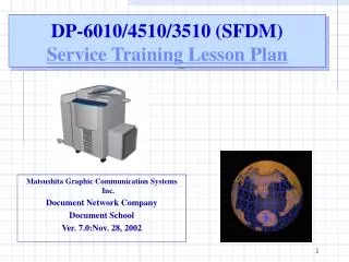
DP-6010/4510/3510 (SFDM) Service Training Lesson Plan. Matsushita Graphic Communication Systems Inc. Document Network Company Document School Ver. 7.0:Nov. 28, 2002. About This Course. Course Title DP-6010/4510/3510 Service Training Duration 4 Days as a standard

E N D
DP-6010/4510/3510 (SFDM)Service Training Lesson Plan Matsushita Graphic Communication Systems Inc. Document Network Company Document School Ver. 7.0:Nov. 28, 2002
About This Course Course Title DP-6010/4510/3510 Service Training Duration 4 Days as a standard Target Audience Service Technicians who are required to install, maintain, diagnose and repair the Panasonic DP-6010 family machines. Prerequisites It is highly recommended that students have an understanding of basic digital copier theory and a familiarity with servicing methods, tools and procedures. Students may bring laptop computers to install print drivers and to exercise the scanner operations. The laptop should operate with Windows 98/ME/NT4.0/XP or 2000. Description This course equips students with the knowledge and skills needed to service the Panasonic DP-6010 series of multifunction machines. The class is designed to allow maximum hands-on time for the students so that they acquire the highest degree of practical experience. The following major topics are included: - Product Overview - Main Unit and Option Installation - Panel Operation - Disassembly and Assembly - Service Mode Explanation - Network Printer Scanner
Course Objectives • Upon completion of this course, you will be able to: • Describe the configurations, features, options, and specifications of the DP-6010/4510/3510 • Install the DP-6010/4510/3510 and perform all required adjustments, including: • Basic Copier • System Console • Finisher(s) • Large Capacity Tray (LCT) • Punch Unit • Optional Memories • Controllers • Scanner • PCL, PDL, Internet Fax/E-mail • Fax Communication • All Additional Options & Accessories Operate the DP-6010 Operator Panel to perform the following functions • Copying, Printing and Faxing • Administrative and Key Operator Settings • Service Mode Functions
Course Objectives (cont'd) • Disassemble and Assemble all major PM and Service components • Use the Service Manual to perform troubleshooting procedures, interpret error codes and isolate failing components • Explain the procedure for locating correct PM Parts, PM Kit and PM Unit Kit • Perform Firmware Update Procedures using the following methods: • Master Flash Memory Card • Network using PC • Describe the procedures for performing the following network functions • Installation of Printer Drivers • Installation and Operation of Panasonic Document Management System software • Scan-to-PC Operation
Training Seminar Policy Time Allocation: Explanation 50% and Hands on 50% • Explanations of: • Machine Feature • Machine Specifications • Machine Configurations • Hands on: • Installation Main Unit & Options • Machine Operation • Disassembly and Assembly • Service Mode Setting • Machine and Materials: • Service Manual • Training machine • PC Network environment
<DP-6010 Training Seminar :Table of Contents> 1. General Specifications 2. Installation / Adjustment 3. General Operation 4. System Description 5. Disassembly / Assembly 6. Service Mode Explanation 7. Printer Scanner Operation 8. Appendix This Lesson Plan is only to serve as an overview of the product and a guidance for service training. Please refer to DP-6010 series Service Manual for the hands on training. This Lesson Plan is based on DP-6010 for discuss purposes.
Section 1 - Objectives At the completion of this section, you will be able to: • Describe characteristics of the DP-6010 family of MFP machines including • New Features • Options Available • Configurations • Specifications • Consumables
Introduction • Product Features • High-speed Digital Copying and Printing. • 60 CPM/ 60 PPM Copy and Print . • Enhanced Graphical User Interface. • Large LCD Touch Panel. • High-Volume Copying Capability. • 1,550 sheets letter size standard paper tray. • Maximum 6,250 sheets with LCT tray(Option) • Versatile Network Capability. • Network Printing, Scanning, Send to E-mail, • Fax Transmission(Option)
SFD-M Positioning SFD-M Series CPM 60 40 SFD-L Series 30 DP-1810 DP-150 20
Product Image Model Item Main specification Remarks 35 45 60 1 2-Bin Finisher DA-FS330 ・1-Bin : Non-sort/100-sheet stack ・2-Bin : Finishing/1000-sheet or 30-sheet x 30-set ・Single-stapling 30-sheet (A4/LT), punch(std) ・Similar to FA-F320 2 1-Bin Saddle Stitch Finisher DA-FS355 ・1-Bin : Finishing 1,000-sheet or 50-sheet x 30-set ・Folding tray : Saddle stitch 10-set(10-sheet) ・Multi-staple : 50-sheet, punch(op) 550 Empty 3 2-Bin Finisher(L) DA-FS600 550 ・1/2-Bin : Finishing 1,000-sheet or 50-sheet x 30-set ・Multi-staple 50-sheet, punch(op) 550 4 2-Bin Saddle Stitch Finisher DA-FS605 ・1/2-Bin : Finishing 1,000-sheet or 50-sheet x 30-set ・Folding tray : Saddle stitch 10-set(15-sheet) ・Multi-staple 50-sheet, punch(op) ・Similar to FA-F365 5 System Console 1 DA-DS601 ・550-sheet tray + storage tray 6 System Console 2 DA-DS602 ・550-sheet tray x 2 7 3000-Sheet Tray DA-MA301 ・Similar to FA-MA301 ・Paper capacity : 3,000-sheet ・Paper size : A4/B5 or LT Mechanical Accessories Under study (Apr ‘2003)
HDD Electrical Accessories Item Image Functions Contents Printer Controller DA-PC600 PCL driver, NW Status Monitor Op-Guide (CD-ROM) 1 PCL6 Printer emulation Key Page Description Language Controller DA-MC600 2 PCL /PS3 driver, NW Status Monitor, Op-Guide (CD-ROM) PCL /PS3 Print Key Tandem Copy,Concurrent Copy Address book, Security Print PS Font, Spooling, Account Manager HDD, HDD Installation kit, Power Supply, Harness Hard Disk Drive Unit DA-HD60 3 Network Scanner DA-NS600 NW scanner(Scan to PC) Document Management Software 4 NW scanner driver, Op-Guide Key 5 Internet Fax/E-Mail DA-NF600 SEND to E-mail (Internet FAX protocol) Internet FAX driver, Op-Guide Key 6 Fax Communication Board DA-FG600 Super-G3 FAX Super-G3 FAX board, Op-Guide Image Memory (D-RAM) DA-SM16B/64B/28B Memory for Sorting/Printing D-RAM board (16/64/128MB) 7 8 Expansion Board DA-EM600 Expansion memory for PCL, PS print F-ROM board (8MB) 9 FLASH MEMORY UE-410047/410048 Expansion memory for facsimile F-ROM card (4/8MB)
DP-3510 Model DP-4510 Model DP-6010 Model Toner ○ ○ × Toner × × ○ Developer ○ July ’02 ○ July ’02 DQ-Z241D DQ-TU35D Drum ○ ○ ○ DQ-H240D DQ-TU24D Commonality of the Consumables ○ : Applicable X : Not Applicable
DP-6010General Specifications • Copier Section • Printer section Specifications for Fax, Scanner and Internet Fax, please refer to the Specifications Table on the Service Manual and User’s Guide.
General Specifications Explanation 1. Main Unit 2. Optional Unit 3. Consumable
*Other Destinations is studying AR600 as an Option for DP3510.
Note:PC600/MC600 will include Expansion Board(EM600) for EU countries. *1: Standard memory 32MB(90 pages)+16MB(45 pages)=> Up to 135 pages capacity. *2: Standard memory 2MB(120 pages)+4MB(240 pages)=> Up to 360 pages capacity. Based on ITU-T test chart No.1 *3: One Expansion Board is needed. Two Boards for Japan. *4: One Expansion Board (EM600) is needed for Japan.
Section 2 - Objectives At the completion of this section, you will be able to: • Install the Main Unit within 30 minutes using the installation instructions contained in the Service Manual. • Perform the following installation adjustments • Toner Density Control • Black Density Sensor Output Gain • Exposure • Install the Options using the installation instructions contained in the Service Manual. • Perform the practical exercise of Installation of Main Unit and Options.
Installation and Adjustment Refer to Installation Manual. 1.Copier 2.Options • Easy Installation of the main unit with the built-in i-ADF • and Duplex within 30 minutes. • Reduced Physical Setup Electronic Access Key for Options.
Installation of Main Unit. (Refer to Installation Instructions of Service Manual) 1.Scanner Unit (1) Remove Blue Screw(Scanner Shipping Screw X1) 2. Fuser Unit Pressure Roller (1) Open the Front Cover. (2) Release the Pressure Roller Spring. 3. OPC Unit (1) Remove the OPC Shipping Metal Bracket. (2) Remove the battery cover sheet under the panel. 4. Developer Unit (1) Release the Developer Unit. (2) Remove the Developer Unit Lid. (3) Pour the Developer into the Developer Unit. 5. Toner Bottle (1) Remove the Toner Bottle cap. (2) Insert the Toner Bottle into the hopper unit. (3) Close the Front Cover. 6. Connect the Power Cord and turn the Power Switch ON. Installation Procedure 1 6 2 3 4 Set the Date & Time by function mode • Perform TDC Adjustment by service mode F8-09. • ( As TDC adjustment time will take 7 min., so other options may be installed during TDC adj.) • (Confirm F6-21:Toner Density Sensor Gain, and F6-26:Sensor Judgment Voltage after TDC setting) • Perform Black Density Sensor output gain Adjustment by service mode F8-14. • Confirm paper size setting of the each tray.
Adjustment Exposure Standard Adjustment 1.Make copy of Test Chart with gray scale (P/N FQ-SJ101 ) by F2 service mode. (Text/Photo mode, Set exposure center) (Ensure F6-17,18 and 19 are set to “0”. Gray scale “1” should not be visible. Gray scale “2” should be clearly visible. 2.Adjust the content of F6-50. The “Reset” key is used to enter the “-”. 3.Adjust F6-49 for Text mode. Adjust F6-51 for Photo mode. Registration & Void Adjustment (Perform in case of necessary) 1.Make copy of Test Chart. 2.Leading edge registration adjustment. F6-03:Original Registration. F6-04: Printer Registration. (+):Paper feed timing is delayed. (-):Paper feed timing is advanced The “Reset” key is used to enter the “-”. F6-91:ADF original lead edge registration. 3.Side edge registration adjustment. F6-11:Laser unit image side(1st tray) F6-12: Laser unit image side(2nd tray) F6-13 :Laser unit image side(3rd tray) F6-14: Laser unit image side(4th tray) 4.Void adjustment. F6-07:Leading edge void adjustment. (+):Void increase(-):Void decrease 1 2 FQ-SJ101 A Not visible 1 Clearly visible 2 3
Optional Unit Installation • Hands on Installation of Optional Kits according to each • Installation Instructions. Then Confirm the Operation. For DP-6010/4510 2-Bin Saddle-Stitch Finisher(FS605) 2-Bin Finisher Inverting ADF (Standard) PCL Controller PDL Controller Expansion Board 8MB (PCL, PS/PCL) Punch Unit DA-SP31 Network Scanner For DP-3510 1-Bin Saddle-Stitch Finisher(FS355) 2-Bin Finisher Note:The 1st Expansion board must be installed into slot 1 for the PCL. Internet Fax/Email Punch Unit for FS355 DA-SP41 Fax Communication Board HDD Image Sort Memory 16M/24M/128MB Flash Memory Card 4/8MB 3000 LCT System Console 550 Sheet X1 Letter-R/Legal Size Adapter System Console 550 Sheet X2 Note: Adjust the Gear Combination of the System console for the DP-6010 because the gear speed is for the DP-3510/4510 as factory setting.
Section 3 - Objectives At the completion of this section, you will be able to: • Use the DP-6010 Operator Panel to perform the following functions • Copying, Printing and Faxing • Administrative and Key Operator Settings
ONLINE ONLINE ENAGY SAVE INTERRUPT FUNCTION RESET Panasonic DP-6010 * REDIAL/ PAUSE COPY ORIGINAL SIZE General Operation COPY SIZE Message Display 1 2 3 STOP CLEAR FAX/EMAIL C FLASH/ SUB-ADDR LEDGER 4 5 6 SCAN/FILE LEGAL START MONITOR 7 8 9 LETTER PRINT SET * 0 # INVOICE Hands on Operation: Refer to the Operating Instructions. Proof Copy 2 in 1 Copy Basic Copy Tandem Copy (Network) Double Sided copy Reduction/ Enlargement Copy Finisher Staple Copy etc.
4 Major Function Keys Copy (Concurrent Copy, Tandem Copy, Remote Copy), Copy Setting Function G3 FAX, Internet FAX, E-Mail Function Network Scanner, Document Management, D.D.Filing Function Mailbox, Security Box, Job Control Function
New Function Proof Copy N sets to Copy Proof Copy 1set for proof N-1set Remaining Copies
New Function Tandem Copy Hands on Time 1. Press [Tandem/Remote] 2. Select destination Device 3. Press [OK] & Copy Start Large Volume Solution: 2 x SFD-M can work jointly to output a copy job Ethernet Original Copy Copy 50% 50% Perform the tandem copy address book setting: Manual registration: Up to 12 address. (Dynamic registration: up to 12 address) Hard disk is required on both units for this operation.
New Function Remote Copy Hands on Time 1. Press [Tandem/Remote] Select Remote Copy. 2. Select destination Device 3. Press [OK] & Copy Start N sets of copies with Finishing Copy Original 100% Remote Operation: Send a copy job to another Copier located in the same Network Domain Hard disk is required on both units for this operation
Job-1 Job-2 Job-3 Job-12 Hands on Time New Function Concurrent Copy Press “RESERVE A JOB” Key Up to 12 different Copy Jobs can be accumulated. (Max. 500 pages: tentative) Hard disk is required for this operation
Function Mode Setting • Perform the practical exercise of Function Mode Setting. Function General Settings Set Key Operator Code “0000” Copier Settings Printer Settings Date Time Setting Scanner Settings TCT/IP Setting 20: Date time setting 22: DHCP default (set “Yes” => ”No”) 23: TCP/IP address 24: TCP/IP subnet mask 25: TCP/IP default gateway 26: DNS server address
Section 4 - Objectives At the completion of this section, you will be able to: • Describe system configuration of the DP-6010 family of MFP machines. • Main Unit • Mechanical Accessories • Electrical Accessories • Imaging Process
System Description • Explain about Copier System Paper Path Inverting ADF Charge Unit OPC Drum Fuser Unit Finisher Developer Unit Punch Unit Sheet Bypass Duplex Unit 3000 Sheet Paper Tray DP-6010/4510 2-Bin Saddle-Stitch Finisher 2-Bin Finisher System Console DP-3510 2-Bin Finisher 1-Bin Saddle-Stitch Finisher
System Configuration Inverting ADF • Explain about System • Configuration and Options. Scanner Unit (SCN PC Board) Panel (PNL PC Board) Main PC Board (SC PC Board: System Control Board) PCL6 Emulation Kit Fax Communication Kit MJR PCB PS/PCL6 Emulation Kit Printer Network Scanner Kit Parallel Port Interface Automatic Duplex Unit Internet Fax Kit 10/100 Ethernet Interface Electronic Sorting Board Expansion Flash Memory Card 4MB, 8MB Hard Disk Kit Image Memory 16, 64, 128MB Option Standard LPC PC Board
Explain System Configuration • and Options. Main PC Board For DP-6010/4510 2-Bin Saddle-Stitch Finisher 2-Bin Finisher (high speed) for DP-3510 2-Bin Finisher 1-Bin Saddle-Stitch Finisher or Exit Tray SPC PC Board (Scanner Printer Control Board) 1,550 Sheet Paper Tray 3000 Sheet Paper Tray 550 Sheet Paper Tray 550 Sheet X1 Paper Tray 550 Sheet X2 Paper Tray Option Standard
Imaging Process • Explain Imaging Process. • Primary Charge:Corona Charge • Imaging:Dual Component Developing • Transfer:Corona Transfer Charger • Separation:Corona Discharge • Cleaning:Urethane Rubber Blade • Process Speed:DP-6010: 350mm/s • 4510: 250mm/s 3510: 180mm/s • Black Solid:More Than 1.1(O.D.=1.0) Laser exposure Corona charger Discharge LED Dr blade Cleaning blade OPC drum Mag-roller Toner density sensor Transfer charger Separation charger
Section 5 - Objectives At the completion of this section, you will be able to: • Remove and Replace the following subassemblies • Sheet Bypass Unit • Paper Feed Module • Drum Unit • Process Unit • Fuser Unit • Automatic Duplex Unit • Scanner Unit • Laser Scanner Unit • Control Panel • PC Boards • SC, SPC, LVPS and other PC Boards • ADF • Options • System console • LCT • Finisher • List the Parts and Parts Kits required for all Preventive Maintenance cycles • Perform the practical exercise of Removal and Replacement of the PM parts.
Hands on Disassembly and Assembly. Refer to the Service Manual how to disassemble. Replace the PM Parts mainly. Disassembly and Assembly • 4. Control Panel Unit • Remove the Lower Panel Cover. • Remove the Control Panel PCB. • 5. Developer Unit • Open the Front Door. • Remove the Developer Unit. • 6. Drum Unit • Loosen 1 screw and remove the Drum Unit. • Remove the F/R Drum Support Bracket. • OPC Drum • Cleaning Blade • Remove the corona charger • 7. Auto Duplex Unit (ADU) • Turn the ADU Unit Lever counter-clockwise. • Note:Keep this Lever position when insert ADU unit • Pull out the ADU Unit. • Remove the Bias Charge Unit. • Remove the Stopper Bracket(Right & Left) • Remove the ADU Unit. • <Procedure of Disassemble with each Unit> • 1. i-ADF • Open the ADF Cover. • Pickup Roller • Paper Feed Roller. • Remove the Lower Opening Guide. • Separation Roller. • 2. Scanner Unit • Remove the Glass assembly. • Xenon Lamp. • Remove the CCD Cover. • Clean the Lens and Mirror. • 3. LSU • Open the Right Cover. • Remove the LSU Cover Bracket. • Remove the Glass Assembly. • Remove the LSU.
The Procedure of Disassembly Instructions are as shown in the Service Manual. • 8. Fuser Unit. • Remove the Fuser Cover. • Note: Push the Release Lever down to • free the exit guide. Keep this position • while insert the fuser unit back. • Remove the Fuser Unit. • Remove the Cleaning Web Unit. • Cleaning Web Roller. • Cleaning Web. • Remove 2 Fuser Lamps. • Thermistor Assembly. • Remove the Upper Fuser Bracket. • Fuser Roller. • Gear, 2 Bearings, 2 Bushing • Fuser Guide • Lower/ Upper Separator • Pressure Roller • Pressure Roller Bearings • 9. Paper Feed Module • Remove the Right Cover. • Pull out the Paper Tray. • Remove the Paper Feed Module. • Feed Roller • Pickup Roller • DFP Roller. • 10. Sheet Bypass Unit • Remove the the Sheet Bypass. • Remove the Bracket. • Pickup Roller • Paper Feed Roller. • 11. PC Boards(SC,SPC,LVPS) • Remove the Rear Plate. • Disconnect all the Harnesses • on the PC Board. • Remove the SC PC Board. • Note: CCD image Sensor Connector • should not to be forced when insert. • Remove the Power Supply.etc. • 12. Options • Disassemble of the Options. • System Console • LCT • Finisher All Students are invited to join in our Hands On Session.
PM Maintenance Blue:Cleaning Black:Replace
Combination Chart PM Kits for DP-6010 Note:Cleaning Blade(DZJN000072) is enhanced to be 240K as PM Cycle and included in a PM parts kit.
Section 6 - Objectives At the completion of this section, you will be able to: • Recognize error codes and messages and determine the recommended procedures to follow in the Service Manual • Enter Service Mode, set parameters and perform typical tests and adjustments • Update the firmware using the master flashcard
Service Mode Explanation 1. Service Mode for Copier Select Service Mode “FUNCTION” Key + “ORIGINAL SIZE LDR/A3” Key + “3” Key Exit Service Mode “FUNCTION” Key + “Clear” Key • Practice with Service Mode Setting for Copier (Refer to the service manual). • F1:Self Test, F2:Single Copy Test, F4:Input/Output Test • F5:Function Parameters, F6:Adjustment Parameters, F7:Electronic Counter • F8:Service Adjustment, F9:Unit Maintenance • 2. Error Code( Refer to Service Manual for Troubleshooting ) • E1:Optical Unit Error,E2:Lift DC Motor Error, E3:Development System Error • E4:Fuser Unit Error, E5:System Error, E7:Optional Error 3. Practice with Service Mode Setting with FAX. Push FAX Key “FUNCTION” Key “MONTOR”X4 times Fax Service Mode + + + * Select No. “STOP” + “STOP” Exit Fax Service Mode
FAX Service Mode Table NO. SERVICE MODE(1-9) ENTER NO. 1.Function Parameter Setting Set Fax Function Parameter (000-299) ex.010:TX Level, 011 RX Level, etc. STOP 1.Function Parameter List 3.Page Memory Test 4.Printer Report(Error Log) 5.All Document Files 6.Protocol Trace 2.RAM Edit Mode 3.Print Parameter List/ Reports (Refer to the RAM Initialization Table / Manual) *:Parameter Initialization 11. Journal Clear 12. Auto Dial Clear 13. Program Dial Clear 14. All Job Clear 15. ID/PSWD Clear 16. Error Log Clear 99. Shipment Set 4.Modem Tests Scroll Down by Invoice/A5 Key Scroll Up by Letter/A4 Key 6.RAM Initialization 1.Service Alert Report 2.Maintenance Alert Report 3.Toner Order Report 6.Customer ID 8.Call Date and Time Setting, etc. 8.Check and Call 9.System Maintenance 1. Firmware Update 2. Firmware Backup 3. Parameter Restore 4. Parameter Backup 5. PC=>Flash Card “Start Key”:The new setting value is stored in the machine.
Firmware Update Main Power SW OFF Main Power SW ON SC/SPC/PNL Update Perform F9-07-00 (Update from master card) Insert appropriate Firmware Card. • Perform hands on firmware update • using FROM Master Card 4MB • Printout Version Information • & F5/F6 parameter data. Firmware Update=> (Green lamp blinks). After completed, the machine reboots itself. Perform F9-06-00. (Parameter initialize) Reprogram F5& F6 parameters. SC Board PANEL Control Board FROM (SC) FROM PNL F-ROM FROM SPC SPC Control Board F-ROM F-ROM Note: Other Update Method 1. The Network Firmware Update Tool via LAN by PC. 2. Firmware Update via local Parallel port by PC. 3. Emergency Update. <Firmware Version Form> Host: DP-SFDM AA V ***** PU Firmware Type A: Standard B: Option Firmware Version Insert Flash ROM card into the socket and turn the power SW ON while energy save key is pressed. (*keep pressed for 20 seconds) Green indicator lights up => Flash =>Blinks=> Off Version Up is completed PNL: SFDM_PNL AAV****** SPC: SFDM_SPC AAV*****
Section 7 - Objectives At the completion of this section, you will be able to: • Install DP-6010 Printer Drivers on a PC • Generate test prints from the PC to the printer via the network • Install and demonstrate Panasonic DMS • Describe the Scan-to-PC "Push" function and required procedures