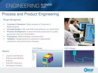
Engineering and Process Control
Feedback control systems are integral in various engineering processes, such as maintaining consistent levels in tanks for production. This project demonstrates a feedback control system designed to keep liquid levels consistent in a cola production process. It explores components like sensors, pumps, and control logic, including reed switches and centrifugal pumps. By understanding concepts such as controlled variables, actuators, and measurement errors, this guide serves as a comprehensive introduction to process control in engineering.

Engineering and Process Control
E N D
Presentation Transcript
Engineering and Process Control You know more than you realize
Introduction • Feedback control is found everywhere • Can be natural or anthropic • Examples: • Electric kettle • Cruise control • Insulin levels • Image Sources • http://www.stashtea.com/mocat.htm • http://www.in.gr/auto/dokimes/pr_dokimes_in/Mazda_6_1800/in_Mazda_6_1800_05.htm • http://www.fda.gov/fdac/features/2002/102_diab.html
How does it work? Controlled Variable (temp, conc., height, speed) Process Actuator Measurement Error (compared to set point) Control (PDI)
Problem Description • To create cola, a company is continuously mixing water and syrup together • Each component comes from a hold tank • These tanks must remain full or else the production process will be interrupted • Design a control system that will maintain the liquid levels • Image Source • http://www.zanesville.ohiou.edu/emedia/Advertising%20archive/
Design Criteria • Tank • Constant liquid level • Draw from a reservoir to the hold tank • Detect low level • Detect full level • Fill tank if required Measure Level Measure Level Full Low Fill Tank No Action
Solution Float Pump Reed switch Height Sensor Fill tank Stop/start + -
Start/Stop – Reed Switch • When a magnet comes close to a reed switch the two paramagnetic contacts become magnetized and attracted to each other (closes the circuit) • This allows an electrical current to pass through • When the magnet is moved away from the reed switch the contacts demagnetize, separate, and move to their original position (opens the circuit) Glass Tube Contacts
Filling the Tank - Basic centrifugal pump • Transfer angular momentum of impeller into kinetic energy of discharged fluid • Faster impeller speed = higher discharge velocity = higher pressure • Bigger housing = larger impeller = higher volumetric flow rate Image Source http://www.yourdictionary.com/ahd/p/p0657700.html
Final Schematic + + - - • Low tank • Primary magnet keeps circuit closed • Pump operational • Full tank • Secondary magnet on float counteracts primary magnet • Circuit opens • Pump deactivated
Final Schematic Photo courtesy of Paul Jowlabar, Lab Manager, Department of Chemical Engineering. Reproduced with permission.
Materials • 3V DC motor • Two AA batteries (each 1.5 V) • 500 mL clear water bottle • AA Battery holder • Electrical wire • Electrical wire clips • 0.5 m of ¼”clear, flexible tubing • Straws • Wooden skewers • Plastic core bard • High density Styrofoam • Two magnets with centre holes • Glue • Reed switch • Small plastic dish • Multimeter
Energy Input • Power input (Win) = AV where: • A = current (A) V = voltage across load (V) V A
Energy Output • Power output (Wout) = Qrgh where: • Q = vol flow rate (m3/s) g = acc. Gravity (m/s2) h = height between pump inlet and outlet (m) r = fluid density (kg/m3) * Q may also be expressed as A(dh/dt) where A is the cross section area of the tank (assuming the tank has uniform A along h.) Q h Fluid input ( r )
Q h Fluid in ( r ) V A Efficiency • Overall pump efficiency = Wout/Win • Pump efficiency is always less than 1 • Source of energy lost: • Electrical resistance • Friction (fluid viscosity, piping, motor) • Impeller (inherent pump efficiency)
Expandability • Alter flexible tube diameter • Adjust size of pump • Change height of inlet and/or outlet • Use other fluids – corn syrup, (thicker than water)