Download
1 / 28
280 likes | 297 Vues
Learn about system behavior and how it is captured in use cases. Understand the interactions between the system and external actors using use case diagrams in UML software design.

E N D
Dynamic Modeling using the Unified Modeling Language (UML) Software Design (UML)
WhatIsSystemBehavior? • System behavior is how a system acts and reacts. • It is the outwardly visible and testable activity of a system. • System behavior is captured in use cases. • Use cases describe the system, its environment, and the relationship between the system and its environment. ٨
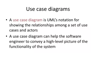
Use Cases • What is a Use Case • A formal way of representing how a business system interacts with its environment. • Illustrates the activities that are performed by the users of the system. • A sequence of actions a system performs that yields a valuable result for a particular actor.
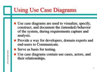
Use Cases • Use case diagramsdepicts the interactions between the system and the external actors. • The emphasis is on what a system does rather than how. • Use case diagrams are closely connected to scenarios. A scenario is an example of what happens when someone interacts with the system.
Key points • The development team, with stakeholders involvement, writes the use cases. • Compared to traditional requirement methods, use cases are relatively easy to write and easier to read. • Free of technical or implementation details.
System name Actor is a stick figure usually an actual person using the system System boundary The use case Connection line shows which actor participate in the use cases
Use-Casecomponents • An actor represents anything that interacts with the system. • An actor might be: • a person • a company or organization, • a computer program, or a computer system • Hardware • A use case is a sequence of actions a system performs that yields an observable result of value to a particular actor. • Name each use case using Noun-Verb. • The communication line to show how the actors communicate with the use case. • Depicted by line or double-headed arrow line Actor • UseCase ٩ OOAD
Use Case Analysis • What is an Actor? • A user or outside system that interacts with the system being designed in order to obtain some value from that interaction • Use Cases describe scenarios that describe the interaction between users of the system (the actor) and the system itself.
A Step-by-Step Guide to Building the Use-Case Model • Step 1: Identify and Describe the Actors • Who uses the system? • Who gets information from this system? • Who provides information to the system? • Where in the company is the system used? • Who supports and maintains the system? • What other systems use this system?
A Step-by-Step Guide to Building the Use-Case Model • Step 2: Identify the Use Cases and Write a Brief Description • What will the actor use the system for? • Will the actor create, store, change, remove, or read data in the system? • Will the actor need to inform the system about external events or changes? • Will the actor need to be informed about certain occurrences in the system?
A Step-by-Step Guide to Building the Use-Case Model • Step 3: Identify the Actor and Use-Case Relationships • Only one actor can initiate a use case • Many use cases may involve the participation of multiple actors. • Each use case is analyzed to see what actors interact with it
Use Cases • Here is a scenario for a medical clinic. • A patient calls the clinic to make an appointment for a yearly checkup. The receptionist finds the nearest empty time slot in the appointment book and schedules the appointment for that time slot. " • We want to write a use case for this scenario. • Remember: A use case is a summary of scenarios for a single task or goal and An actor is who or what initiates the events involved in the task of the use case.
Use Cases • So as we read our scenario, what or who is the actor???? • The actor is a Patient. • So What is the Use Case???? • The Use Case is Make Appointment.
Use Cases • The picture below is a Make Appointment use case for the medical clinic. • The actor is a Patient. The connection between actor and use case is a communication association (or communication for short). Actors are stick figures. Use cases are ovals. Communications are lines that link actors to use cases.
Use Case • Boundary • A boundary rectangle is placed around the perimeter of the system to show how the actors communicate with the system. Make Appointment
Use-Case Diagram A use case diagram is a collection of actors, use cases, and their communications.
Use Case Diagram • Other Types of Relationships for Use Cases • Generalization • Include • Extend
Generalization Relationship • Much like superclasses in a class diagram • A generalized use case represents several similar use cases • One or more specializations provides details of the similar use cases • Represented by a line and a hollow arrow • From child to parent Parent use case
Invoking use case Included use case <<include>> Include Relationship • use cases that are included as parts of other use cases. • You have a piece of behavior that is similar across many use cases • Break this out as a separate use-case and let the other ones “include” it • Arrow is drawn from the base use case to the used use case • Write << include >> above arrowhead line
Base use case Extending use case <<extend>> Extend relationship • use cases that extend the behavior of other core use cases. • A use-case is similar to another one but does a little bit more • Put the normal behavior in one use-case and the exceptional behavior somewhere else • Arrow is drawn from the extension use case to the base use case • Write << extend >> above arrowhead line
Purchase Item <<include>> Verify Credit card Examples • Include • Extend
Example • Suppose we want to develop software for an alarm clock. The clock shows the time of day. Using buttons, the user can set the hours and minutes fields individually, and choose between 12 and 24-hour display. It is possible to set one or two alarms. When an alarm fires, it will sound some noise. The user can turn it off, or choose to ’snooze’. If the user does not respond at all, the alarm will turn off itself after 2 minutes. ’Snoozing’ means to turn off the sound, but the alarm will fire again after some minutes of delay. • Try to model it with a use case diagram.