Download
1 / 61
610 likes | 850 Vues
Smart Grid Technology Information - May 2010. Date: 2010-5-05. Abstract: Information on 802.11 technology for inclusion in the June 2010 NIST PAP#2 Report. Agenda. Status Report on Connectivity Week - Santa Clara May 24-28 Any other items from members. Status report.

E N D
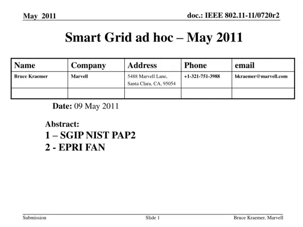
Smart Grid Technology Information - May 2010 Date: 2010-5-05 Abstract: Information on 802.11 technology for inclusion in the June 2010 NIST PAP#2 Report Bruce Kraemer, Marvell
Agenda Status Report on Connectivity Week - Santa Clara May 24-28 Any other items from members Bruce Kraemer, Marvell
Status report Connectivity Week - Santa Clara May 24-28 • Included meetings for SGIP & P2030 • Most of the SGIP DEWGs & PAPs held working meetings • P2030 held 4 days of meetings Bruce Kraemer, Marvell
P2030 Overview • Standard Title • IEEE P2030 Draft Guide for Smart Grid Interoperability of Energy Technology and Information Technology Operation with the Electric Power System (EPS), and End-Use Applications and Loads • Scope This document provides guidelines for smart grid interoperability. This guide provides a knowledge base addressing terminology, characteristics, functional performance and evaluation criteria, and the application of engineering principles for smart grid interoperability of the electric power system with end-use applications and loads. The guide discusses alternate approaches to good practices for the smart grid. Bruce Kraemer, Marvell
P2030 Highlights P2030 held 4 days of meetings • Primary activity was review and proposed edits of Draft 2.1 • https://mentor.ieee.org/2030/dcn/10/2030-10-0242-00-0015-p2030-draft-2-1-with-line-numbers-added.pdf • Most time spent in each group refining the diagrams • Comments collected will be incorporated during June • Draft 3.0 due out for comment in July http://grouper.ieee.org/groups/scc21/2030/2030_index.html Bruce Kraemer, Marvell
SGIP Events • SGIP Plenary Meetings and Webinars (attendance required for participating members) • Meeting NameTypeDate/Times of upcoming meetingsRegistration • Spring Meeting Face-to-Face May 24 to May 27 Agenda for week. • Plenary Update Webinar July 23rd, 1pm to 3pm Eastern To register and receive web/phone access • Plenary Update Webinar Sept. 17th, 1pm to 3pm Eastern To register and receive web/phone access • Plenary Update Webinar Oct. 29th, 1pm to 3pm Eastern To register and receive web/phone access • Fall Meeting Face-to-Face Nov. 30 to Dec. 3 Current details. Further details to post in early October. Bruce Kraemer, Marvell
Near Term Action Items Completion for review of PAP#2 report Section 4 (Wireless) Current version of overall report can be found at: http://collaborate.nist.gov/twiki-sggrid/pub/SmartGrid/PAP02Wireless/NIST_Priotity_Action_Plan_2_r04.pdf Next Call Wednesday June 9 (877) 627-6785 00692 Status report on all activities for IEEE 802 July Plenary Bruce Kraemer, Marvell
Previous Discussion Material Bruce Kraemer, Marvell
Introduction to the NIST PAP2 Report • Report Preface • This guide is the output of the Priority Action Plan number 2 (PAP#2), wireless communications for the smart grid, which is part of the Smart Grid Interoperability Panel (SGIP). PAP#2’s work area investigates the strengths, weaknesses, capabilities, and constraints of existing and emerging standards-based physical media for wireless communications. The approach is to work with the appropriate standard development organizations (SDOs) to determine the characteristics of each technology for Smart Grid application areas and types. Results are used to assess the appropriateness of wireless communications technologies for meeting Smart Grid applications’ requirements. • This guide contains the smart grid reference architecture, the user applications’ requirements, candidate wireless technologies and their capabilities, a methodology to assess the appropriateness of wireless communications technologies along with an example model, and some results. Bruce Kraemer, Marvell
Draft r4 Report Outline • Table of Contents • Revision History ............................................................................................................................................. iii • Preface ...................................................................................................................................................... - 1 - • Authors ...................................................................................................................................................... - 2 - • 1 Overview of the process .................................................................................................................... - 3 - • 2 Acronyms and Definitions.................................................................................................................. - 4 - • 2.1 Acronyms ........................................................................................................................................ - 4 - • 2.2 Definitions ....................................................................................................................................... - 7 - • 3 Smart grid....................................................................................................................................... - 11 - • 3.1 Reference Architecture................................................................................................................... - 11 - • 3.2 List of actors.................................................................................................................................. - 13 - • 3.3 Use Cases..................................................................................................................................... - 14 - • 3.4 Application requirements................................................................................................................ - 16 - • 3.4.1 Smart grid user applications’ quantitative requirements......................................................... - 16 - • 3.4.2 Aggregation of requirements per actor to actor...................................................................... - 16 - • 4 Wireless Technology ....................................................................................................................... - 20 - • 5 Evaluation approach / Modeling approach ...................................................................................... - 21 - • 5.1 Channel Models ............................................................................................................................. - 23 - • 5.1.1 Indoor-indoor environments ................................................................................................... - 24 - • 5.1.2 Outdoor-outdoor environments .............................................................................................. - 25 - • 5.1.3 Outdoor-indoor environments ................................................................................................ - 25 - • 5.2 Physical Layer............................................................................................................................... - 26 - • 5.3 MAC sublayer................................................................................................................................ - 26 - • 5.4 Example Modeling Tool.................................................................................................................. - 26 - • 5.5 Other Tools ................................................................................................................................... - 27 - • 6 Findings / Results........................................................................................................................... - 28 - • 7 Conclusions.................................................................................................................................... - 31 - • 8 References ..................................................................................................................................... - 32 - • 9 Bibliography.................................................................................................................................... - 32 - Bruce Kraemer, Marvell
Section 4 – Wireless Technology -Contents Outline • Introduction • The data collection form • Group categories • Row descriptions • Clarification of the row entry • Technology information (Columns) • Technology names • Technology sources • Explanation of Entries & Validation source • Per Technology descriptions • Completed • Under development • Reference Sources Bruce Kraemer, Marvell
Wireless Characteristics • 1. Link Availability • 2. Data/Media Type Supported • 3. Coverage Area • 4. Mobility • 5. Data Rates • 6. RF Utilization • 7. Data Frames & Packets • 8. Link Quality Optimization • 9. Radio Performance Measurment & Management • 10. Power Management • 11. Connection Topologies • 12. Connection Management • 13. QoS & Traffic Prioritization • 14. Location Characterization • 15. Security & Security Management • 16. Radio Environment • 17. Intra-technology Coexistence • 18. Inter-technology Coexistence • 19. Unique Device Identification • 20. Technology Specification Source • 21. Deployment Domain Characterization • 22. Exclusions Bruce Kraemer, Marvell
Wireless Technologies • Cdma2000 1x and cdma2000 HRPD • Cdma2000 xHRDP • GMR-1 3G • IPOS/DVB-S2 • RSM-A • IEEE 802.16 e,m • IEEE 802.11 • IEEE 802.15 • Inmarsat BGAN • LTE • HSPA+ • UMTS • EDGE Bruce Kraemer, Marvell
Technology Description and Behavior in support of Throughput calculations Range Calculations Security Bruce Kraemer, Marvell
Technology Description Clarifications Bruce Kraemer, Marvell
Group 2: Data/Media Type Supported, b: Data; • 2.1 Group 2: Data/Media Type Supported, b: Data; • Over the air PHY rate • What is the meaning of Data? It is in measurement units of Maximum user data rate per user in Mb/s. • Since 802.15.4 gives 0.25 Mb/s one might assume that it is the physical medium rate. However with that assumption, it does not apply to the value for 802.11 of 0.70 Mb/s. • Therefore one must assume another meaning. For example data rate minus protocol (and/or framing) overhead results in 0.70 Mb/s (i.e., maximum user data rate (i.e., MAC Service Data Unit)), if so then the 802.15.4 value must be changed to comply with that assumption. • Agreement on a consistent meaning of Data is needed. • Is it the maximum user data rate seen at the interface to/from the MAC sublayer? • Is it an instantaneous data rate? • Since it states Maximum user data rate per user, perhaps the number of users that was assumed for the calculation needs to be stated as well, especially when the medium is shared as in 802.11 and 802.15.4. Bruce Kraemer, Marvell
2.3 Group 5: Data Rates items c and d (Peak goodput over the air UL/DL data rate) • How is the goodput calculated? • Is goodput strictly calculated on a single MAC sublayer frame’s payload divided by the resulting physical layer packet? • Is the goodput calculated including any CSMA overhead and the entire message exchange (e.g., data frame and acknowledgement frame)? • Both 802.11 and 802.15.4 can act as either peer to peer (p2p) or AP to/from STA for 802.11 or coordinator to/from device for 802.15.4. So for the peer case UL and DL would be the same. However for the non-P2P case UL and DL might be different. Both 802.11 and 802.15 use the same channel in this case, but the protocol overhead might be different (e.g., polling a PAN coordinator to retreive data vs device sending to PAN coordinator for 802.15.4). Clarification (i.e., note) on the type of mode that is being used to achieve the values for the data rates is needed. Bruce Kraemer, Marvell
2.3.2 Sample peak goodput for 802.11 baseline • Was not able to obtain 0.7 Mb/s, assuming only data transmission overhead for one data frame transmission and its associated acknoledgement. What other additional overhead assumptions were assumed? Beacon transmission? RTS/CTS? Association and authentication procedures? • 2.3.2.1 (A) • Assuming one message exchange of one 50us DIFS + zero backoff + long preamble (144) + PLCP (48) + 28 bytes MAC overhead + 2312 bytes user data (maximum) + 10 us SIFS + ACKnowledgement packet under DCF; a peak throughput of 0.959 Mb/s. • 2.3.2.2 (B) • Assuming one message exchange of one 50us DIFS + 15.5 backoff slots (average first attempt successful)+ long preamble (144) + PLCP (48) + 28 bytes MAC overhead + 2312 bytes user data (maximum) + 10 us SIFS + ACKnowledgement packet under DCF and DS; a peak throughput of 0.944 Mb/s. Bruce Kraemer, Marvell
Group 7, Data frames and packets, item a frame duration and item b Maximum packet size What is meant by frame? What is meant by packet? Are they the same or different? Bruce Kraemer, Marvell
2.4 Group 7, Data frames and packets, item a frame duration and item b Maximum packet size Sample explanation What is meant by frame? There are three primary Frame group types identified in 802.11 Management, Control & Data. Payload data is transported inside a data frame. The Data Frame is composed of a number of sub fields: control field, duration field, address fields, sequence field, data, frame check sequence. This collection of fields is referred to as a MAC Protocol Data Unit (MPDU). The source payload data may fit into one frame or if larger than 2312 bytes requires fragmentation and transmission using multiple data frames. When the MPDU is prepared to send out over the air there are additional fields added for preamble, start of frame delimiter and header. These fields then comprise the Physical Layer Packet Data Unit (PPDU). What is meant by packet? “Packet” is a general term that refers to the combination of control, address, and data fields described above that includes the payload data of interest . Are they the same or different? When the terms Packet and Frame are used without further qualifiers they can be considered to be equivalent. Bruce Kraemer, Marvell
Technology Description Protocol Details Bruce Kraemer, Marvell
802.11 MAC and Physical Layer Data Frame Encapsulation(Ref: Draft P802.11-REVmb/D3.0, March 2010) MSDU LLC Frame Control (2 bytes) Duration /ID (2 bytes) Address1 (6 bytes) Address2 (6 bytes) Address3 (6 bytes) Sequence. Control (2 bytes) QoS Control (2 bytes) HT Control (2 bytes) MAC MAC Header CCMP Header (8 bytes) MSDU MIC (8 bytes) Frame CheckSum(4 bytes) MPDU PLCP Preamble PLCP Header PSDU Tail Pad Bytes PHY PHY Layer Specific PPDU ( Example : OFDM Phy , Clause 17) Bruce Kraemer, Marvell
802.11 MAC and Physical Layer Control Frame Encapsulation(Ref: Draft P802.11-REVmb/D3.0, March 2010) LLC Optional Control Info (BlockAck and BlockAckReq) Carried Frame Control HT Control Carried Frame Frame Control (2 bytes) Duration /ID (2 bytes) Address1 (6 bytes) OptionalAddress2 (6 bytes) MAC Optional Control Info MAC Header Optional Control Info Frame CheckSum(4 bytes) MPDU PLCP Preamble PLCP Header PSDU Tail Pad Bytes PHY PHY Layer Specific PPDU ( Example : OFDM Phy , Clause 17) Bruce Kraemer, Marvell
802.11 MAC and Physical Layer Management Frame Encapsulation(Ref: Draft P802.11-REVmb/D3.0, March 2010) LLC Frame Control (2 bytes) Duration /ID (2 bytes) Address1 (6 bytes) Address2 (6 bytes) Address3 (6 bytes) Sequence. Control (2 bytes) HT Control (2 bytes) Management Frame Body LLC MAC MAC Header Management Frame Body Frame CheckSum(4 bytes) MMPDU PLCP Preamble PLCP Header PSDU Tail Pad Bytes PHY PHY Layer Specific PPDU ( Example : OFDM Phy , Clause 17) Bruce Kraemer, Marvell
802.11 MAC and Physical Layer Management Frame Encapsulation(Ref: Draft P802.11-REVmb/D3.0, March 2010) LLC Frame Control (2 bytes) Duration /ID (2 bytes) Address1 (6 bytes) Address2 (6 bytes) Address3 (6 bytes) Sequence. Control (2 bytes) HT Control (2 bytes) Management Frame Body LLC MAC MAC Header Management Frame Body Frame CheckSum(4 bytes) MMPDU PPDU PHY PHY Layer Specific PPDU ( Example : OFDM Phy , Clause 17) Bruce Kraemer, Marvell
Framing http://forskningsnett.uninett.no/wlan/throughput.html Bruce Kraemer, Marvell
Resulting Data Message sizes (for this selection) On-demand meter read 100 bytes TLS 25 bytes Transport TCP 20 bytes IP-SEC (Tunnel mode) 80 bytes IPv6 40 bytes IEEE 802.11 CCMP 16 bytes IEEE 802.11 28 bytes DSSS 24 bytes ---------------------------------------------------------------------- TOTALS 333 bytes Similarly for Application Error on-demand meter read TOTALS 283 bytes Similarly for Multiple interval meter read TOTALS 1833 bytes - 2833 bytes* *Exceeds MTU of 802.11 must segment into two frames http://collaborate.nist.gov/twiki-sggrid/pub/SmartGrid/PAP02Wireless/March31NISTPresentation.ppt Bruce Kraemer, Marvell
Technology Description PHY Details Bruce Kraemer, Marvell
802.11a Throughput Bruce Kraemer, Marvell
Behavior Bruce Kraemer, Marvell
Example throughput calculations - #1 1Mbps PHY rate, DCF, single sender to receiver pair, no backoff Bruce Kraemer, Marvell
Example throughput calculations - #2 1Mbps PHY rate, DCF, single sender to receiver pair, minimal backoff Bruce Kraemer, Marvell
MPDU Structure MAC Header Variable length frame body containing payload data Frame Check Sequence • A question of how much detail to provide? • How to account for variables such as security options? PPDU Structure Preamble Header MPDU Bruce Kraemer, Marvell
Throughput Question • 2.3.2.1 (A) • Assuming one message exchange of one 50us DIFS + zero backoff + long preamble (144) + PLCP (48) + 28 bytes MAC overhead + 2312 bytes user data (maximum) + 10 us SIFS + ACKnowledgement packet under DCF; a peak throughput of 0.959 Mb/s • Again, how much detail to provide? • What is precise enough? • How to account for theory vs practice? Bruce Kraemer, Marvell
Example 1: 11b 2Mbps Measured Throughput Analyzing Wireless LAN Security Overhead Harold Lars McCarter Thesis submitted to the Faculty of the Virginia Polytechnic Institute and State University in partial fulfillment of the requirements for the degree of Master of Science in Electrical Engineering 17-Apr-06Falls Church, Virginia http://scholar.lib.vt.edu/theses/available/etd-04202006-080941/unrestricted/mccarter_thesis.pdf Bruce Kraemer, Marvell
Example 2: Various 802.11 Reported Throughputs Huawei Quidway WA1006E Wireless Access Point http://www.sersat.com/descarga/quidway_wa1006e.pdf Bruce Kraemer, Marvell
Behavior Bruce Kraemer, Marvell
Relationship betweenThroughput and Payload Throughput High SNR Low SNR Lower SNR Payload Length Bruce Kraemer, Marvell
Effect of payload length on throughput for various retransmission limits (6 Mbps, SNR of 2 dB) Bruce Kraemer, Marvell
Throughput versus payload (18 Mbps, SNR 8dB) 10.66 Mbps 59.2% Bruce Kraemer, Marvell
Capacity with 5 data users in thenetwork (SNR is 8 dB , 6 Mbps) Bruce Kraemer, Marvell
Individual 802.11 station Bruce Kraemer, Marvell
Group of 802.11 stations Bruce Kraemer, Marvell
802.11 Inter-frame Spacing Bruce Kraemer, Marvell
Frame Spacing Relationships • aSIFSTime and aSlotTime are fixed per PHY. • aSIFSTime is: aRxRFDelay + aRxPLCPDelay + aMACProcessingDelay + aRxTxTurnaroundTime. • aSlotTime is: aCCATime + aRxTxTurnaroundTime + aAirPropagationTime • + aMACProcessingDelay. • The PIFS and DIFS are derived by the following equations, as illustrated in Figure 9-12. • PIFS = aSIFSTime + aSlotTime • DIFS = aSIFSTime + 2 × aSlotTime • The EIFS is derived from the SIFS and the DIFS and the length of time it takes to transmit an ACK Control • frame at the lowest PHY mandatory rate by the following equation: • EIFS = aSIFSTime + DIFS + ACKTxTime • where • ACKTxTime is the time expressed in microseconds required to transmit an ACK frame, including • preamble, PLCP header and any additional PHY dependent information, at the lowest PHY • mandatory rate. Bruce Kraemer, Marvell
PHY Header Details • The value of the TXTIME parameter returned by the PLME_TXTIME.confirm primitive shall be calculated • according to Equation (19-9): • TXTIME = PreambleLengthDSSS + PLCPHeaderTimeDSSS • + PreambleLengthOFDM + PLCPSignalOFDM • + 4 × Ceiling((PLCPServiceBits + 8 × (NumberOfOctets) + PadBits) / NDBPS) + SignalExtension(19-9) • where • PreambleLengthDSSS is 144 μs if the PREAMBLE_TYPE value from the TXVECTOR parameter • indicates “LONGPREAMBLE,” or 72 μs if the PREAMBLE_TYPE value • from the TXVECTOR parameter indicates “SHORTPREAMBLE” • =144+48 or 24+8+ Bruce Kraemer, Marvell
802.11 Preamble PreambleThe preamble is used to communicate to the receiver that data is on its way. Technically speaking, it is the first portion of the Physical Layer Convergence Protocol/Procedure (PLCP) Protocol Data Unit (PDU). The preamble allows the receiver to acquire the wireless signal and synchronize itself with the transmitter. A header is the remaining portion and contains additional information identifying the modulation scheme, transmission rate and length of time to transmit an entire data frame. Long Preamble: • Compatible with legacy IEEE 802.11 systems operating at 1 and 2 Mbps (Megabits per second) • PLCP with long preamble is transmitted at 1 Mbps regardless of transmit rate of data frames • Total Long Preamble transfer time is a constant at 192 usec (microseconds) Short Preamble: • Not compatible with legacy IEEE 802.11 systems operating at 1 and 2 Mbps • PLCP with short preamble: Preamble is transmitted at 1 Mbps and header at 2 Mbps • Total Long Preamble transfer time is a constant at 96 usec (microseconds) Bruce Kraemer, Marvell
802.11 MCS options for “a” & “g” Bruce Kraemer, Marvell