Download
1 / 24
240 likes | 382 Vues
More on gas filled rf cavities Alvin Tollestrup RF One Day Workshop Oct 15, 2008. From D. J. DeBritetto and L. H. Fisher, PR 104, 1213 ,(1956). n(x) = n(0) Exp( a x). = .001 p (torr) = .001 (800 / 14.7 760) = 41.4

E N D
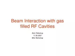
More on gas filled rf cavities Alvin Tollestrup RF One Day Workshop Oct 15, 2008
From D. J. DeBritetto and L. H. Fisher, PR 104, 1213 ,(1956) n(x) = n(0) Exp(ax) • = .001 p (torr) = .001 (800 / 14.7 760) = 41.4 This is for a parallel plate chamber. In an RF cavity, the charges oscillate back and forth and if E / P > 14.5, the density will grow with each cycle and will propagate along the E axis. When the charge density becomes big enough, the end fields will grow and a will increase until the channel connects the two ends of the cavity. A second way propagation can take place is shown below: Threshold n(x) = n(0) Exp(ax) /[1 - g( Exp(ax)-1)] • Represents feed back to the cathode and can be due to positive ion bombardment or photo emission. Even a very small g like .001 can lead to run away! For linear part of the curve, pick the point at 800 psi and 60 MV/m E/p = ( 60 104 volts/cm) / ( 800 psi / 14.7 760) = 14.5 V/cm/mmHg ie: 1/e distance = ¼ mm
Positive - - - - - - - - E increasesd at ends ++++++++ Negative
Note the increase of 5/cycle At 50 MV/m From David Rose, Voss Scientific See LEMC 2008
Consider locations C andD Point c has an E / P of about 0.6 x 14.5=8.7 So an avalanche with gas multiplication cannot form unless some mechanism pushes the local field up to 100 MV/m. The limit is sensitive to the material and even more important Mahzad has produced measurements showing an En dependence on field where n is 7, 10 and 11.4 for Be, W and Mo respectively. E/p = 14.5 along this line Postulated process: At the peak of the rf, something injects a burst of electrons from the negative plate. This instantaneous local cloud of charge enhances the local field to 100 MV / m and an avalanche starts and propagates across the cavity. Sources of electron burst: 1. Field emission from microscopic points of metal. 2. Places of low work function on the metal. 3. Field ionization of the Hydrogen molecule (field ion microscopes). 4. Possibly thermal emission during the process.
Fowler- Nordheim Region J[ E, wf} = 154 (E2/ wf) Exp[-6830 v[x] wf1.5 / E] amps / cm2 wf = workfunction, eV E in MV/m and v[x] is a slowly varying function of x = E / wf1/2. v[0] = 1 and v[ 15 GV/m / 4.561/2 ] = 0. The latter value is for Tungsten. It is normally set equal to 1. J[T] / J[0} = 1 + 4 T2 wf / E2 in units above. At E = 1000 MV/m and tungsten at 1000 the factor is about 20. So increasing temperature can have an important effect.
J[ E, wf} = 154 (E2/ wf) Exp[-6830 v[x] wf1.5 / E] amps / cm2 Get E from n and then get j from E
So from the slope at breakdown, we can calculate the field and the current density. Field ionization of H2 requires fields > 22 GV/m so this doesn’t happen How does one get such high fields? b is used to measure the ratio of the field strength derived from field emission to the cavity and for tungsten is 8.3 109 / 60 106 = 1400. Small regions of low work function can help but don’t give the full effect. Variation of workfunction is less than a factor of 4. Also no variation of E for moderate changes in temperature.
Projections can appear in times as short as ms! Little & Smith JAP 1964
Tungsten electrodes Tomaschkte & Alpert 1964 JAP Top: After heating to 1600 oC for 2 min. Bottom: projections caused by breakdown
Since the breakdown gradient is 60 MV/m and we need about 8 GV/m, we need a field enhancement of about 1250. From the model above we can calculate the h/r ratio. A ratio of about 30 will give the required fields.
Properties of electrode material jMIITS Consider current flowing thru tungsten. Conservation of energy requires: j(t)2r(T) dt = Cp (T) density dT for a 1 cm cube. This can be Recast to: jMIITS(T) = If T is the melting point, then this tells us how much j(t)2dt We need to reach melting or any state at temperature T. We calculate this for several elements.
We see tungsten melt, so w know that we reach jMIIT = 3 108 amp2 sec. Note that copper is harder to melt than tungsten. jMIIT does not include the heat of fusion, which is quite large (see above table).
Back to the Paschen region. What are all those little points doing? 1. Locally the field is way above the avalanche region. The points are still emitting electrons. J is about 10^6 a/cm^2. Suppose the area is 10 microns^2 then the current is about 1 amp. The top of the rf cycle is about 0.1 ns so the break down current is charge injected is about 6 10e9 electrons. We see from the curve below that at ¼ the break down voltage there are still a few electrons/cycle injected.
1. It would be interesting to simulate (Voss) what happens around a sharp point with injection of various amounts of charge in both the Paschen region and in the 60 MV/m region. A 2D simulation showing how things propagate would be nice. • Could one glue down the projections with ALD? • Can we get better measurements of the field index? • Does one see light from the projections in the non-breakdown Paschen region? • Some Questions
After breakdown we have an equivalent circuit for the cavity. • What can we learn from discharge? • The equivalent circuit is shown to the left. The arc has an inductance given by L = mo / 2 p Log[r1/r2] and a resistance due to electrons collision. L f L C r 1 / Z[p]=1/pL + pC + 1/(pfL+r) Cubic with 3 roots, 1 real, 2 complex.
f=6 R=100
Current thru arc, normalized to 1.8 MV across cavity. For 10m diameter arc and 1000 A, J= 1.3 10e9 A/cm2