Understanding the OSI Model: A Comprehensive Guide to Computer Networks
This document provides an in-depth exploration of the OSI model in computer networking, detailing each of its seven layers: Physical, Data Link, Network, Transport, Session, Presentation, and Application. It highlights the significance of networking for communication efficiency and resource sharing, alongside the associated architectures and protocols that facilitate the interconnection of diverse systems. The content emphasizes the practical applications of networking, such as email, video conferencing, and centralized databases, making it essential for students and professionals alike.

Understanding the OSI Model: A Comprehensive Guide to Computer Networks
E N D
Presentation Transcript
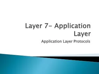
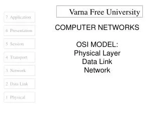
Varna Free University 7 Application COMPUTER NETWORKS OSI MODEL: Physical Layer Data Link Network 6 Presentation 5 Session 4 Transport 3 Network 2 Data Link 1 Physical
7 Application 6 Presentation • Source • Computer Networks, Andrew S. Tanenbaum • www.cisco.com • www.novell.com • www.rad.com • www.3com.com 5 Session 4 Transport 3 Network 2 Data Link 1 Physical
7 Application 6 Presentation 5 Session 4 Transport INTRODUCTION 3 Network 2 Data Link 1 Physical
7 Application NETWORK GOALS • The two main benefits of networking computers are… • Communications • Information can be distributed very quickly, such as email and video conferencing. • Saving Money • Resources such as information, software, and hardware can be shared. • CPUs and hard disks can be pooled together to create a more powerful machine. 6 Presentation 5 Session 4 Transport 3 Network 2 Data Link 1 Physical
7 Application APPLICATIONS • A lot of things we take for granted are the result of computer networks. • Email • Chat • Web sites • Sharing of documents and pictures • Accessing a centralized database of information • Mobile workers 6 Presentation 5 Session 4 Transport 3 Network 2 Data Link 1 Physical
7 Application NETWORK STRUCTURE • The subnet interconnects hosts. • Subnet • Carries messages from host to host. It is made up of telecommunication lines (i.e. circuits, channels, trunks) and switching elements (i.e. IMPs, routers). • Hosts • End user machines or computers. • Q: Is the host part of the subnet? 6 Presentation 5 Session 4 Transport 3 Network 2 Data Link 1 Physical
7 Application NETWORK ARCHITECTURES • A set of layers and protocols is called the network architecture. • 1. Protocol Hierarchies • Networks are organized as layers to reduce design complexity. Each layer offers services to the higher layers. Between adjacent layers is an interface. • Services – connection oriented and connectionless. • Interface – defines which primitives and services the lower layer will offer to the upper layer. • Primitives – operations such as request, indicate, response, confirm. 6 Presentation 5 Session 4 Transport 3 Network 2 Data Link 1 Physical
7 Application NETWORK ARCHITECTURES • 2. Design Issues for the Layers • Mechanism for connection establishment • Rules for data transfer • Error control • Fast sender swamping a slow receiver • Inability of processes to accept long messages • Routing in the case of multiple paths 6 Presentation 5 Session 4 Transport 3 Network 2 Data Link 1 Physical
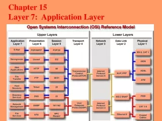
7 Application OSI REFERENCE MODEL • The Open Systems Interconnection is the model developed by the International Standards Organization. • Benefits • Interconnection of different systems (open) • Not limited to a single vendor solution • Negative Aspect • Systems might be less secure • Systems might be less stable 6 Presentation 5 Session 4 Transport 3 Network 2 Data Link 1 Physical
7 Application OSI REFERENCE MODEL • 1. Physical Layer • a) Convert the logical 1’s and 0’s coming from layer 2 into electrical signals. • b) Transmission of the electrical signals over a communication channel. • Main topics: • Transmission mediums • Encoding • Modulation • RS232 and RS422 standards • Repeaters • Hubs (multi-port repeater) 6 Presentation 5 Session 4 Transport 3 Network 2 Data Link 1 Physical
7 Application OSI REFERENCE MODEL • 2. Data Link Layer • a) Error control to compensate for the imperfections of the physical layer. • b) Flow control to keep a fast sender from swamping a slow receiver. • Main topics: • Framing methods • Error detection and correction methods • Flow control • Frame format • IEEE LAN standards • Bridges • Switches (multi-port bridges) 6 Presentation 5 Session 4 Transport 3 Network 2 Data Link 1 Physical
7 Application OSI REFERENCE MODEL • 3. Network Layer • a) Controls the operation of the subnet. • b) Routing packets from source to destination. • c) Logical addressing. • Main topics: • Internetworking • Routing algorithms • Internet Protocol (IP) addressing • Routers 6 Presentation 5 Session 4 Transport 3 Network 2 Data Link 1 Physical
7 Application OSI REFERENCE MODEL • 4. Transport Layer • a) Provides additional Quality of Service. • b) Heart of the OSI model. • Main topics: • Connection-oriented and connectionless services • Transmission Control Protocol (TCP) • User Datagram Protocol (UDP) 6 Presentation 5 Session 4 Transport 3 Network 2 Data Link 1 Physical
7 Application OSI REFERENCE MODEL • 5. Session Layer • a) Allows users on different machines to establish sessions between them. • b) One of the services is managing dialogue control. • c) Token management. • d) Synchronization. 6 Presentation 5 Session 4 Transport 3 Network 2 Data Link 1 Physical
7 Application OSI REFERENCE MODEL • 6. Presentation Layer • a) Concerned with the syntax and semantics of the information. • b) Preserves the meaning of the information. • c) Data compression. • d) Data encryption. 6 Presentation 5 Session 4 Transport 3 Network 2 Data Link 1 Physical
7 Application OSI REFERENCE MODEL • 7. Application Layer • a) Provides protocols that are commonly needed. • Main topics: • File Transfer Protocol (FTP) • HyperText Transfer Protocol (HTTP) • Simple Mail Transfer Protocol (SMTP) • Simple Network Management Protocol (SNMP) • Network File System (NFS) • Telnet 6 Presentation 5 Session 4 Transport 3 Network 2 Data Link 1 Physical
7 Application SERVICES • Each layer provides services to the layer above it. • 1. Terminologies • Entities – active elements in each layer (e.g. process, intelligent I/O chip). • Peer Entities – entities in the same layer on different machines. • Service Provider – Layer N. • Service User – Layer N + 1. • Service Access Points – places where layer N + 1 can access services offered by layer N. 6 Presentation 5 Session 4 Transport 3 Network 2 Data Link 1 Physical
7 Application SERVICES • 2. Connection-Oriented and Connectionless • Connection-Oriented – before data is sent, the service from the sending computer must establish a connection with the receiving computer. • Connectionless – data can be sent at any time by the service from the sending computer. • Q: Is downloading a music file from the Internet • connection-oriented or connectionless? • Q: Is email connection-oriented or connectionless? 6 Presentation 5 Session 4 Transport 3 Network 2 Data Link 1 Physical
7 Application SERVICES • 3. Service Primitives • Request– entity wants the service to do some work • Indicate – entity is to be informed about an event • Response – entity responds to an event • Confirm – entity is to be informed about its request • Sending Computer Receiving Computer 6 Presentation 5 Session 4 Transport 3 Network 2 Data Link 4 Transport 4 Transport 1 Physical 1. request 4. confirm 2. indicate 3. response 3 Network 3 Network
7 Application BANDWIDTH • The capacity of the medium to transmit data. • Analog Bandwidth • Measurement is in Hertz (Hz) or cycles/sec. • Digital Bandwidth • Measurement is in bits per second (bps). • Q: Is 100MHz = 100Mbps? • Q: Is 100Mbps = 100MBps? 6 Presentation 5 Session 4 Transport 3 Network 2 Data Link 1 Physical
Hello 7 Application AH Hello 6 Presentation PH AH Hello 5 Session SH PH AH Hello 4 Transport TH SH PH AH Hello 3 Network NH TH SH PH AH Hello 2 Data Link DH NH TH SH PH AH Hello DT 1 Physical Bits
7 Application 6 Presentation 5 Session 4 Transport PHYSICAL LAYER 3 Network 2 Data Link 1 Physical
7 Application OVERVIEW • Signals • Fourier analysis • Maximum data rate of a channel • Transmission Media • Guided and Unguided • Analog Transmission • Modulation • Modems • RS-232, RS-422 • Digital Transmission • Encoding schemes • Repeaters and hubs • Transmission and Switching • Multiplexing (FDM and TDM) • Circuit vs. packet switching 6 Presentation 5 Session 4 Transport 3 Network 2 Data Link 1 Physical
7 Application SIGNALS • 1. Fourier Analysis • a) All signals can be represented mathematically. • b) A periodic function can be constructed by adding a number of sine and cosine functions. • Fundamental frequency – where f = 1/T • Harmonics – integer multiples of the fundamental frequency • Baud– number of signal level changes per second • Q: Is baud and data rate different terms? • Q: Is 1 baud equal to 1bps? 6 Presentation 5 Session 4 Transport 3 Network 2 Data Link 1 Physical
7 Application SIGNALS • 2. Maximum Data Rate of a Channel • Nyquist • Maximum data rate = 2H log2V (bits/sec) • H = line bandwidth • V = a signal with V discrete levels • Example: • A noiseless 3kHz channel cannot transmit binary (2 level) signals at a rate faster than 6000bps • 2(3k) log22 = 6000bps 6 Presentation 5 Session 4 Transport 3 Network 2 Data Link logAV = (1 / ln A) ln V 1 Physical
7 Application SIGNALS • Shannon • Maximum data rate (bits/sec) = H log2(1+ PS/PN) • H = line bandwidth • PS = signal strength in watts • PN = noise strength in watts • Example: • A 3kHz channel with a noise ratio of 30dB • (PS/PN = 1000) cannot transmit at a rate faster than 30,000bps • (3k) log2(1001) = 30,000bps • Note: SNR = 10log10(PS/PN) 6 Presentation 5 Session 4 Transport 3 Network 2 Data Link 1 Physical
7 Application SIGNALS • 3. Attenuation vs. Amplification • Attenuation • The signal received is weaker than the signal sent. • Attenuation (dB) = 10log10(P1/P2) • Amplification • The signal received is stronger than the signal sent. • Amplification (dB) = 10log10(P2/P1) • Note: • P1 = transmitted signal power in watts • P2 = received signal power in watts • Q: If the result of the attenuation formula is negative, what • happened to the signal? 6 Presentation 5 Session 4 Transport 3 Network 2 Data Link 1 Physical
7 Application TRANSMISSION MEDIA • 1. Guided • Data is sent via a wire or optical cable. • Twisted Pair • Two copper wires are twisted together to reduce the effect of crosstalk noise. (e.g. Cat5, UTP, STP) • Baseband Coaxial Cable • A 50-ohm cable used for digital transmission. Used in 10Base2 and 10Base5. • Broadband Coaxial Cable • A 75-ohm cable used for analog transmission such as Cable TV. 6 Presentation 5 Session 4 Transport 3 Network 2 Data Link 1 Physical
7 Application TRANSMISSION MEDIA • Fiber Optic Cables • Two general types are multimode and single mode. • In multimode, light is reflected internally. Light source is an LED. • In single mode, the light propagates in a straight line. Light source come from expensive laser diodes. Faster and longer distances as compared to multimode. • * Fiber optic cables are difficult to tap (higher security) • and are normally used for backbone cabling. 6 Presentation 5 Session 4 Transport 3 Network 2 Data Link 1 Physical
7 Application TRANSMISSION MEDIA • 2. Unguided • Data is sent through the air. • Line-of-sight • Transmitter and receiver must “see” each other, such as a terrestrial microwave system. • Communication Satellites • A big microwave repeater in the sky. Data is broadcasted, and can be “pirated.” • Radio • Term used to include all frequency bands, such as FM, UHF, and VHF television. 6 Presentation 5 Session 4 Transport 3 Network 2 Data Link 1 Physical
7 Application ANALOG TRANSMISSION • 1. Modulation • Modulating a sine wave carrier to convey data. • Amplitude Modulation (AM) • Amplitude is increased/decreased while frequency remains constant. • Frequency Modulation (FM) • Frequency is increased/decreased while amplitude remains constant. • Phase Modulation • Wave is shifted, while amplitude and frequency remains constant. 6 Presentation 5 Session 4 Transport 3 Network 2 Data Link 1 Physical
7 Application ANALOG TRANSMISSION • 2. Modems • A device that accepts digital signals and outputs a modulated carrier wave, and vice versa. • It is used to interconnect the digital computer to the analog telephone network. • * Modems for PC’s can be external or internal. • * Nokia makes modems for leased line connections. 6 Presentation 5 Session 4 Transport 3 Network 2 Data Link 1 Physical
7 Application ANALOG TRANSMISSION • 3. RS-232 and RS-449 • Two well known physical layer standards. • RS-232 • 20 kbps • Cables up to 15 meters • Unbalanced transmission (common ground) • RS-422 • 2 Mbps at 60 meters • 1 Mbps at 100 meters • Balanced transmission (a pair of wires for Tx, Rx) 6 Presentation 5 Session 4 Transport 3 Network 2 Data Link 1 Physical
7 Application DIGITAL TRANSMISSION • 1. Encoding Schemes • Converting logical data into electrical signals suitable for transmission. • Manchester • Mid bit transition for clock synchronization and data • Logic 0 = high to low transition • Logic 1 = low to high transition • Differential Manchester • Mid bit transition for clock synchronization only • Logic 0 = transition at the beginning of each bit period • Logic 1 = no transition at the beginning of each bit period 6 Presentation 5 Session 4 Transport 3 Network 2 Data Link 1 Physical
7 Application DIGITAL TRANSMISSION • 2. Repeaters and Hubs • These are physical layer devices. • Repeaters • Restores the strength of an attenuated signal. • Used to increase the transmission distance. • Does not filter data traffic. • Hubs • Multi-port repeater. • Interconnects several computers. • Does not filter data traffic. 6 Presentation 5 Session 4 Transport 3 Network 2 Data Link 1 Physical * Picture from 3com.com
7 Application 6 Presentation 5 Session 4 Transport NETWORK LAYER 3 Network 2 Data Link 1 Physical
7 Application OVERVIEW • Routing Algorithms • Shortest Path • Flooding • Flow-based • Distance Vector • Link State • Hierarchical • Broadcast • Multicast • Routing for Mobile Hosts • Congestion control • IP Addressing • Routers 6 Presentation 5 Session 4 Transport 3 Network 2 Data Link 1 Physical
7 Application ROUTING ALGORITHMS 1. Shortest Path 6 Presentation C(B,3) B(A,2) 5 Session B C 1 2 2 4 Transport 3 3 A(-,-) D(E,3) 2 A D F(E,4) 3 Network 1 F 1 E(A,2) 2 2 2 Data Link E 1 Physical A – E – D – F A – E – F is the answer.
7 Application ROUTING ALGORITHMS 2. Flooding 6 Presentation Packet to IMP C 5 Session IMP B Packet Packet to IMP D 4 Transport Packet to IMP E To prevent packets from circulating indefinitely, a packet has a hop counter. Every time a packet arrives at an IMP, the hop counter is decrease by 1. Once the hop counter of a packet reaches 0, the packet is discarded. 3 Network 2 Data Link 1 Physical
7 Application IP ADDRESSING Format x x x x x x x x . x x x x x x x x . x x x x x x x x . x x x x x x x x where x is either 0 or 1 Example 1: 1 1 1 1 1 1 1 1 . 1 1 1 1 1 1 1 1 . 0 0 0 0 0 0 0 0 . 0 0 0 0 0 0 0 0 255.255.0.0 Example 2: 1 1 1 1 1 1 1 1 . 1 1 1 1 1 1 1 1 . 1 0 0 0 0 0 0 0 . 0 0 0 0 0 0 0 0 255.255.192.0 6 Presentation 5 Session 4 Transport 3 Network 2 Data Link 1 Physical
7 Application IP ADDRESSING Network Address Example 1: IP address of computer 180.100.7.1 Mask 255.255.0.0 Network address 180.100.0.0 Example 2: IP address of computer 180.100.7.1 Mask 255.255.255.0 Network address 180.100.7.0 Example 3: IP address of computer 180.100.7.2 Mask 255.255.192.0 Network address 180.100.0.0 6 Presentation 5 Session 4 Transport 3 Network 2 Data Link 1 Physical
7 Application IP ADDRESSING • Mask • Valid mask are contiguous 1’s from left to right. • Examples: • Valid • 255.0.0.0 • 255.255.0.0 • 255.255.255.0 • Invalid • 255.1.0.0 • 255.0.255.0 • 255.255.64.0 • 200.255.0.0 6 Presentation 5 Session 4 Transport 3 Network 2 Data Link 1 Physical
7 Application IP ADDRESSING Subnets The Internet is running out of IP address. One solution is to subnet a network address. This is done by borrowing host bits to be used as network bits. Example: Class B mask 255.255.0.0 Borrowing 1 bit gives a subnet mask of 255.255.128.0 Borrowing 2 bits gives a subnet mask of 255.255.192.0 Borrowing 3 bits gives a subnet mask of 255.255.224.0 Borrowing 4 bits gives a subnet mask of 255.255.240.0 6 Presentation 5 Session 4 Transport 3 Network 2 Data Link 1 Physical
7 Application IP ADDRESSING • Example: • Given an IP address of 180.200.0.0, subnet by borrowing 4 bits. • Subnet mask = 255.255.240.0 • The 4 bits borrowed are value 128, 64, 32, 16. This will create 16 sub networks, where the first and last will be unusable. • Sub network address: • 180.200.0.0 • 180.200.16.0 • 180.200.32.0 • 180.200.48.0 • 180.200.64.0 • etc… 6 Presentation 5 Session 4 Transport 3 Network 2 Data Link 1 Physical
7 Application IP ADDRESSING The first 3 usable sub networks are: 180.200.16.0 180.200.32.0 180.200.48.0 For sub network 180.200.16.0, the valid IP address are: 180.200.16.1 to 180.200.31.254 Directed broadcast address is: 180.200.31.255 6 Presentation 5 Session 4 Transport 3 Network 2 Data Link 1 Physical
7 Application ROUTERS A layer 3 device that is used to interconnect 2 or more logical networks. Can filter broadcast traffic, preventing broadcast traffic from one network from reaching another network. 6 Presentation 5 Session 4 Transport 180.200.0.0 202.5.3.0 3 Network 2 Data Link 1 Physical