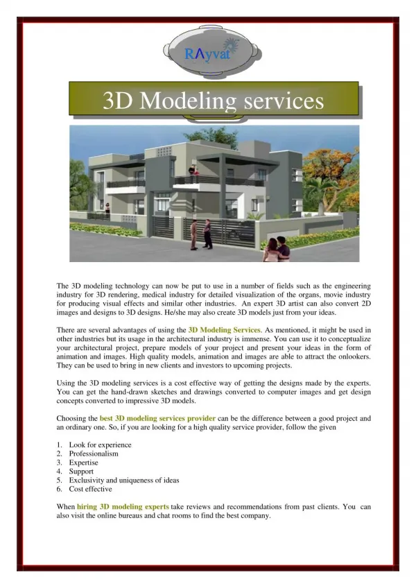
3D Computer Modeling
3D Computer Modeling. Using Inventor. 3D Modeling in Inventor. Getting Started This is what you will see when you first open Inventor. You can begin a new file or open an existing file with either the New or Open commands on the Launch panel, the Quick Access Toolbar, or the Application Menu.


3D Computer Modeling
E N D
Presentation Transcript
3D Computer Modeling Using Inventor
3D Modeling in Inventor Getting Started This is what you will see when you first open Inventor. You can begin a new file or open an existing file with either the New or Open commands on the Launch panel, the Quick Access Toolbar, or the Application Menu. When selecting New, be sure to choose the correct system, either English or Metric.
Application Menu Contains common commands for creating, saving, and printing. Quick Access Toolbar Provides quick access to frequently used commands Ribbon A palette that displays buttons and controls used for both 2D drawing and annotation and 3D modeling and viewing Ribbon Tabs Organized by task, contain task specific buttons and controls Graphics Window The active modeling area where parts and assemblies are created and edited Inventor Screen Layout Application Menu Quick Access Toolbar Ribbon Ribbon Tabs Graphics Window
Inventor Screen Layout • View Cube • Clickable and draggable interface that is used to switch between standard and isometric views • Navigation Bar • On screen element that provides access to various navigation tools • Browser • Maintains history of part, assembly, or drawing creation • 3D Indicator • Shows direction of X, Y, and Z coordinates. • Red represents X, • Green represents Y • Blue represents Z directions Browser View Cube Navigation Bar 3D Indicator
Dynamic Viewing Functions Located on View Ribbon Tab Used to Zoom and Pan to reposition the sketch
Precise Input • The Precise Input toolbar is added by expanding the Draw panel and selecting Precise Input • Create the shapes that you labeled in Activity 1.5.1 The Coordinate System and Descriptive Geometry.
Left Mouse Button Used to select icons, menus, and graphics Right Mouse Button Brings up additional options Accepts default option Ends a process Middle Button/Wheel Provides quick pan and zoom functions Mouse Buttons
Geometric Constraints Symbols that show alignments to capture the design intent To use Geometric Constraints: 1. Use the commands available from the Sketch panel 2. Right mouse click in Graphics Window, then select Create Constraint OR
Image Resources Microsoft, Inc. (2008). Clip Art. Retrieved November 4, 2008, from http://office.microsoft.com/en-us/clipart/default.aspx