Download
1 / 20
200 likes | 287 Vues
This study explores the use of Computational Fluid Dynamics (CFD) in ship design for atmospheric research, including the challenges, processes, and available CFD codes. It addresses issues such as flow distortion effects and the importance of accurate modeling for research vessels. The presentation also covers the parametric method proposed for efficient ship shape transformations.

E N D
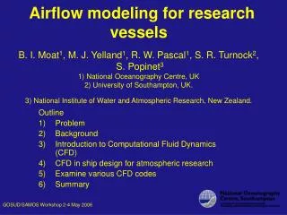
Airflow modeling for research vesselsB. I. Moat1, M. J. Yelland1, R. W. Pascal1, S. R. Turnock2, S. Popinet31) National Oceanography Centre, UK2) University of Southampton, UK.3) National Institute of Water and Atmospheric Research, New Zealand. Outline • Problem • Background • Introduction to Computational Fluid Dynamics (CFD) • CFD in ship design for atmospheric research • Examine various CFD codes • Summary GOSUD/SAMOS Workshop 2-4 May 2006
Problem • Finding a measure of the acceleration/deceleration at any given instrument location • Determining the effective measurement height (vertical displacement of air) • Developing an effective tool that can be used during the ship design phase to best site atmospheric instrumentation • Order 50 ships? - balance between time/finanical cost etc GOSUD/SAMOS Workshop 2-4 May 2006
Background • The effects of flow distortion: • are not that sensitive to variations in wind speeds between 6 to 20 ms-1 (<0.5%) • are very sensitive to relative wind direction and anemometer location (20 %) • are sensitive to the ship design (~5%) (VOSClim brochure) GOSUD/SAMOS Workshop 2-4 May 2006
The 4 stage CFD modelling process • 1) Geometry creation • Digitize plans (autocad) • Femgen (Femsys, UK) • 4 WEEKS PER SHIP • Or, obtain model from naval architects • Significant learning curve GOSUD/SAMOS Workshop 2-4 May 2006
The 4 stage CFD modelling process • 1) Geometry creation • 2) Mesh generation High resolution mesh • Historically the most difficult part of CFD modelling • Variable mesh sizes and types • Different mesh for each wind direction GOSUD/SAMOS Workshop 2-4 May 2006
The 4 stage CFD modelling process • 1) Geometry creation • 2) Mesh generation • 3) Compute solution • Run times are machine dependant (1 - 10 days) • 64 bit workstation • 1- 3 Gbytes memory 10 m/s 15 m/s GOSUD/SAMOS Workshop 2-4 May 2006
The 4 stage CFD modelling process • 1) Geometry creation • 2) Mesh generation • 3) Compute solution • 4) Post-processing • Estimate wind speed bias and vertical displacement 10 m/s 15 m/s GOSUD/SAMOS Workshop 2-4 May 2006
Research ship design • RRS Charles Darwin • 5% wind speed error due to ship structure • RRS Discovery • Streamlined • Wind speed errors (bow-on 1%) GOSUD/SAMOS Workshop 2-4 May 2006
Research ship design RRS James Cook to be delivered in September 2006 GOSUD/SAMOS Workshop 2-4 May 2006
Research ship design RRS James Cook RRS Discovery Wind speed bias (%) RRS Charles Darwin Relative wind direction Request a streamlined superstructure Foremast as tall and far forward as possible Uncluttered foremast platform GOSUD/SAMOS Workshop 2-4 May 2006
CFD CODES available • VECTIS - www.ricardo.com • Cost: $11k academic license ($5.4k per additional processor) • Accuracy: 2% for low flow distortion sites (up to 10% bias) • Best validated • 11 ships modeled - (Yelland et al. 2002) • Fast mesh generation process (staff time = 3 hours/run) • Computation times of 3-5 days per relative wind direction GOSUD/SAMOS Workshop 2-4 May 2006
CFD CODES available • VECTIS - www.ricardo.com • Cost: $11k academic license ($5.4k per additional processor) • Accuracy: 2% for low flow distortion sites (up to 10% bias) • Best validated • 11 ships modeled - (Yelland et al. 2002) • Fast mesh generation process (staff time = 3 hours/run) • Computation times of 3-5 days per relative wind direction • FLUENT - www.fluent.com • Cost: $?k depends upon application (equivalent to VECTIS ) • Accuracy: ? % • 1 ships modeled - Dupuis et al. (2003) • Mesh generation process • Initial Staff time = 2 weeks • Less for other wind directions • Computation times of 1 day GOSUD/SAMOS Workshop 2-4 May 2006
CFD CODES available • GERRIS- gfs.sourceforge.net • Cost: FREE (GNU software license) • Accuracy: 4% (1 ships modeled - Popinet et al. 2004) • University of Tokyo are currently modeling 2 ships (part of a PhD. Project) • Mesh generation fully automatic • Mesh adapts to the flow where specified • Computation times vary 3 to 5 days (depends on geometry detail required) GOSUD/SAMOS Workshop 2-4 May 2006
New ‘parametric method’ proposed by Ship Science • Assumption: hulls are similar and geometries don’t need to be accurate everywhere • Script to transform ship shape into representations of other ships (each deck xyz +position rel. to bow) • Investigate the level of detail required GOSUD/SAMOS Workshop 2-4 May 2006
New ‘parametric method’ proposed by Ship Science • Automatic generation of the large scale geometry • Detailed foremast model added for each ship • Automatic mesh generation for each wind direction • Flow then simulated in FLUENT or CFX GOSUD/SAMOS Workshop 2-4 May 2006
Possible parametric method projects? • Project based at Ship Science, Southampton University, UK with NOC advising • Initial feasibility study to determine accuracy of method - needs $27k funds • Full scale project aimed at modelling a significant fraction of the 50 ships - needs at least $36k/year funds GOSUD/SAMOS Workshop 2-4 May 2006
Comparison of approaches • Present detailed geometry approach • GERRIS/VECTIS/FLUENT for 1 ship at 10 wind direction: • 8 weeks staff plus analysis time • 5 to 10 weeks computation • OK for a low number of ships • Of known accuracy • Time scale: could start now (given staff time and software) • NOC would make avaialble existing geometries of the RV Ron Brown, RV Knorr and FS Polarstern GOSUD/SAMOS Workshop 2-4 May 2006
Comparison of approaches • Parametric geometry and mesh creation • Once developed, for 1 ship at 10 wind directions: • about 2 days staff plus analysis time • 1 day computation (parallel processing) • Feasible for studying the airflow over 50 ships • Accuracy not known yet • Validate by comparison to existing detailed models • Lead time: active research area which requires funding GOSUD/SAMOS Workshop 2-4 May 2006
SAMOS aims • Accuracy required? • What relative wind directions to study? • Number of ships to study? • When ? • Funding ? GOSUD/SAMOS Workshop 2-4 May 2006
CONTACTS • VECTIS - ben.moat@noc.soton.ac.uk www.noc.soton.ac.uk/JRD/MET/cfd_shipflow.php • GERRIS - s.popinet@niwa.co.nz http://gfs.sourceforge.net • NEW PARAMETRIC METHOD - S.R.Turnock@ship.soton.ac.uk GOSUD/SAMOS Workshop 2-4 May 2006