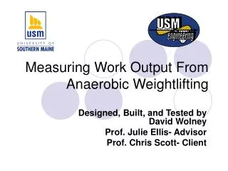
Measuring Work Output in Weightlifting: A Novel Approach by David Wolney
110 likes | 230 Vues
This project, designed by David Wolney with guidance from Professors Julie Ellis and Chris Scott, focuses on quantifying work output during weightlifting to establish a correlation between the work done and calories burned. The innovative system uses a Smith machine equipped with a rotary encoder that measures cable travel, enabling precise calculations of distance and work output. Through detailed analysis of the lift, including work, power, and velocity, significant insights into weightlifting efficiency are gained. The preliminary tests have shown promising results in meeting client needs.

Measuring Work Output in Weightlifting: A Novel Approach by David Wolney
E N D
Presentation Transcript
USM engineering Measuring Work Output From Anaerobic Weightlifting Designed, Built, and Tested by David Wolney Prof. Julie Ellis- Advisor Prof. Chris Scott- Client
Professor Chris Scott of the Department of Exercise, Health, and Sport Sciences needed a means of measuring work output done by a weightlifter. How much work am I doing? • Prof. Scott hopes to find a correlation between work output and calories burned. Work Calories
Clarifying the problem: what, exactly is required for measurement Work = Force X Distance • Actual work done during a set is zero. • Only positive displacement is counted. • Force is the force required to overcome gravity and lift the weight. • The average force during the lift is the force required to hold position, this is equal to the weight being lifted. • The only required measurement is distance.
The Smith machine, like many weight machines, utilizes a cable that is attached to the moving weight. Pulley Another pulley wheel with an encoder is attached to the machine to measure the cable travel Weight Counterweight Using a digital rotary encoder to measure the cable travel
Radius=0.5 cm 3.14 cm Rotary encoder theory of operation An encoder disk has alternating light and dark wedges and two photodetectors. This example disk has 4 light-dark transitions per revolution (0.785 cm in this example) Left-US Digital Encoder, Above-signal from encoder; A and B are in quadrature. This arrangement allows for determination of direction as well as improved resolution
The Intel 8051 microcontroller provides the interface. The encoder wheel attaches to the Smith machine The 8051’s serial port allows for detailed data of the lift on a PC Encoder Wheel Counterweight Weight lifted The 8051 Development Board from PJRC works well in this application Work Done: Lots of clicks The display gives the distance lifted in “clicks”
The processor counts transitions • Signal A is monitored for a high-low transition • When A goes high, B is checked to determine direction • Absolute count is incremented or decremented, as applicable • Positive distance count is incremented if direction is up • The absolute count is regularly sent to the serial port and the positive count is sent to the LCD display
A PC can collect the data from the serial port so that it can be processed 00000003 00000005 00000008 00000009 00000011 00000011 00000014 00000016 00000017 00000020 00000024 00000028 00000032 00000037 00000041 00000047 00000052 00000060 00000067 00000073 00000080 00000085 00000091 00000097 00000106 00000115 00000127 00000144 00000158 00000169 00000179 00000187 00000196 00000203 00000210 00000218 00000224 00000229 00000241 00000256 00000267 00000276 00000287 00000294 00000299 00000300 00000300 00000300 00000300 00000304 00000315 00000336 00000351 00000357 00000367 00000381 00000399 Raw data is collected. The data contains distances and, implicitly, time A detailed analysis of the lift can be done. Knowing distance, time, and weight allows determination of many different statistics of the lift. Work, power, velocity, acceleration and others can be calculated
Measuring Wheel Smith Machine Client Controller The first prototype has been installed and some preliminary tests have been performed. The wheel installed
Reading in “CLICKS” Some refinements were necessitated by the preliminary tests. A keypad allows entry of weights 8-bit counters free up the processor Prof. Scott prefers to have more information on the display of the device. He found the detailed computer analysis less useful for his purposes, so efforts were focused away from the computer interface
The encoder wheel attaches to the Smith machine The revised system better fits the client’s needs. Work Done and Seconds Clock The display gives more information A keypad allows entry of weights External 8-bit counters count the encoder clicks and free the processor for other tasks The PC is treated as an optional component