David Post v. Crane Rigging Corp.
This document presents a preliminary reconstruction of an accident involving improper rigging of an 80-foot long truss during construction at Blevins Building Supply Co. The presentation includes detailed assessments of the accident sequence, site plans, and improper rigging methods that resulted in a severe injury to a worker. Key findings indicate critical flaws in rigging practices and the importance of adhering to safety guidelines. Visual aids illustrate truss lifting operations and stress calculations to analyze the failure points during the incident.


David Post v. Crane Rigging Corp.
E N D
Presentation Transcript
David Post v. Crane Rigging Corp. Preliminary Reconstruction PresentationDrake Exhibits 2-26-08 DRAFT
Accident site overview DRAFT Blevins Building Supply Co. - Site Plan
US highway 21 new warehouse construction main office / store DRAFT Blevins Building Supply Co. - Site Plan
date of accident - 00-00-00 US highway 21 new warehouse construction main office / store DRAFT Plan View - Blevins Building Supply Co.
DRAFT New warehouse construction
roof trusses set exterior wall framing stack of roof trusses to be set DRAFT New warehouse construction
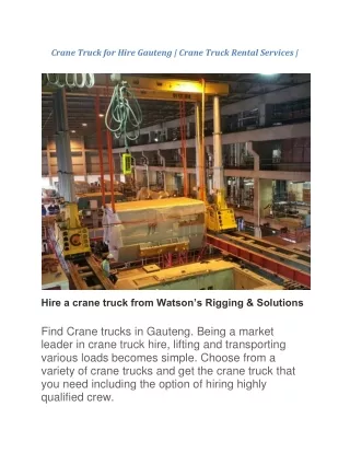
show crane Trusses are lifted by crane and set on top of exterior wall frame DRAFT New warehouse construction
Accident Sequence DRAFT
DRAFT Trusses are stacked in parking lot
DRAFT Trusses are rigged to crane using a spreader bar approx. 20’ long
DRAFT Spreader bar is attached to truss with chains at each end
DRAFT Truss is lifted to vertical from stack
DRAFT Truss bends and tilts when lifted off stack
DRAFT A tag line is used to control movement of the truss
DRAFT Truss bends and flops around while being moved to building
DRAFT Truss is swung around to south end of building
DRAFT Truss is moved to the north
Randall ________ David Post & Roger Billings DRAFT Worker positions on scissor lifts
Randall ________ David Post & Roger Billings DRAFT Truss is lowered toward final position
David Post & Roger Billings DRAFT Truss breaks at attachment point severely injuring David Post
Rigging Trusses DRAFT
Chain angle more than 60º Spreader bar only attached at ends Spreader bar is too high on truss Spreader bar is too short 80 Feet DRAFT Accident rigging dangerously inadequate for 80 foot long truss
Chain angle 60º or less Attachment points to truss at a maximum of 10 foot intervals Locate spreader bar at or above mid-height Spreader bar is 2/3 to 3/4 truss length 80 Feet DRAFT Proper method for rigging an 80 Foot Long Truss From BCSI-B1 Guide for Handling, Installing, Restraining & Bracing of Trusses
1. Calculation of Stress and Deformation of the Truss During Lifting Operations ANSYS Finite Element Analysis computer software used for all results Actual incident truss geometry and material properties incorporated in analysis Truss lifting points obtained from witness statements DRAFT
1. Calculation of Stress and Deformation of the Truss During Lifting Operations DRAFT
2. Animation of Truss Deformation During Lifting Operation DRAFT This movie will play automatically - click to stop
3. Animation of Truss Deformation During Lifting Operation - close up of maximum stress location DRAFT Click this movie to play - click again to stop
5. Validation of the Computer Model of the Truss Measure actual load-displacement response of an exemplar truss at Tru-Line Truss Company Compare the measured values with that predicted by the computer model DRAFT
Modeling Stresses in Wooden Trusses During Lifting and Moving DRAFT
Improper method of rigging DRAFT Trusses are improperly rigged using a spreader bar approx. 20’ long
Highest stress is at the point of attachment DRAFT Stress shown in truss structure as truss is lifted off pile
DRAFT Truss bends and twists when lifted using inadequate rigging
DRAFT Truss breaks at point of attachment to spreader bar
Proper method of rigging DRAFT Trusses are rigged to crane using a spreader bar approx. 60’ long
DRAFT Stress shown in truss structure as truss is moved to building
DRAFT Stress shown in truss structure as truss is set and fastened to top plate
END Drake Exhibits - Demonstrative Evidence Services 1275 Main Street Brewster, MA 02631 508-255-8194 www.Drake-Exhibits.com DRAFT