Download

1 / 17
170 likes | 332 Vues
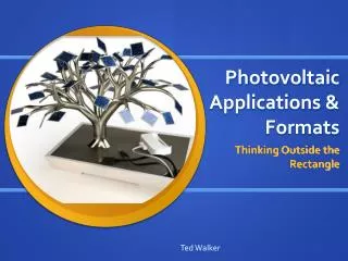
Applications of Photovoltaic Technologies. Solar cell structure. How a solar cell should look like ? It depends on the function it should perform, it should convert light into electricity, with high efficiency. It should be a P-N junction. It should absorb all light falling on it

E N D
Solar cell structure • How a solar cell should look like ? • It depends on the function it should perform, it should convert light into electricity, with high efficiency • It should be a P-N junction • It should absorb all light falling on it • It should reflect less light • Most of the light should go in N-type P-type • There should be ohmic contact at both side • It should convert all absorb light into electricity
Solar Cell-structure Busbar Antireflection coating Fingers Emitter Antireflection texturing (grid pattern) Base Rear contact • A solar cell is a P-N junction device • Light shining on the solar cell produces both a current and a voltage to generate electric power.
Minimizing optical losses • There are a number of ways to reduce the optical losses: . • Anti-reflection coatings can be used on the top surface of the cell. • Reflection can be reduced by surface texturing • The solar cell can be made thicker to increase absorption • The optical path length in the solar cell may be increased by a combination of surface texturing and light trapping. • Top contact coverage of the cell surface can be minimized
Optical properties of surface • Photons in the spectrum can generate EHP, ideally all the sun light • falling on the cell should be absorbed • Short circuit current (ISC) is usually reduced due to optical losses What are optical losses: Reflection Shadowing due to metal contact Partial absorption • Design criteria for small optical losses : • Mminimize optical loss
Choice of ARC Air, n0 ARC, n1 Semiconductor, n2 • The thickness of a ARC is chosen such that the reflected wave have destructive interference this results in zero reflected energy n2 > n1 > n0 • The thickness of the ARC is chosen so that the wavelength in the dielectric material is one quarter the wavelength of the incoming wave (destructive interference).
Reflection from various combination • Index of refraction is also a function of wavelength, minimum reflection is obtained for one wavelength • Multilayer structure reduces the reflection losses • More than one ARC can be used, but expensive Source: PV CDROM - UNSW
Surface texturing • Any rough surface decreases the reflection by increasing the chances of the reflected rays bouncing back on the surface • Surface texturing can be obtained by selectiveetching a process by which material is removed by chemical reaction • Selective etching is based on the concept of different material property in different direction in crystals, • Etching rate are different in <100> dirn than in <111> dirn
Surface texturing <111> surface • Chemical etching in KOH results in pyramid formation on the Si surface etching is faster in <100> direction than in <111> direction • Using photolithography, inverted pyramids can be obtained, which are more effective
Light trapping • Rear side reflector or rear side texturing is used to increase the optical path length in solar cell Increased optical path is required for thin solar cell (thin solar cell have higher Voc. It saves expensive Si) • Total internal reflection (TIR) condition are used to increase the optical path length Snell’s law For TIR (1 for Si is 36 degree)
Lambertian Rear Reflectors TIR • Lambertian reflector is one which reflects the lights in a random direction this together with the front texturing increases the optical path length • Increases the path length by 4n2, very good in light trapping, path ;length increases by about 50 Random reflector from the rear side
Current loss due to recombination Front surface P-N junction Bulk semiconductor rear surface • Recombination of carriers reduces both short circuit current as well as open circuit voltage • Recombination areas • Surface recombination • Bulk recombination • Depletion region recombination • Design criteria: The carrier must be generated within a diffusion length of the junction, so that it will be able to diffuse to the junction before recombining
Top contact w d h h w Emitter • One example of top metal contact design • Design criteria:minimize losses (resistive, shadow) • finger and busbar spacing, • the metal height-to-width, aspect ratio, • the minimum metal line width and • the resistivity of the metal
Resistive Losses: Series resistance, Rs Fingers Contributing factors to Rs : Bus bar 1. the movement of current through the emitter and base of the solar cell M-S contact N-layer p-layer emitter Base 2.the contact resistance between the metal contact and the silicon 3. resistance of the top and rear metal contacts
Contact resistance • Metal to semiconductor contact • Heavy doping under contact to minimize contact resistance • N • Contact resistance losses occur at the interface between the silicon solar cell and the metal contact. To keep top contact losses low, the top N+ layer must be as heavily doped as possible. • Ohmic contact, • High doping, tunneling contact • A high doping creates a "dead layer“.
Sheet resistance L t W • In diffused semiconductor layers, resistivity is a strong function of depth. It is convenient to a parameter called the "sheet resistance" (Rs). • Rs is called sheet resistance with unit of ohms/square or Ω/□ (actual unit is Ohms) • The L/W ratio can be thought of as the number of unit squares (of any size) • Sheet resistance of a solar cell emitter is in the range of 30 to 100 Ω/□
Emitter resistance: Power loss t • N • P d/2 d L dx x • Zero current flow exactly at midpoint of fingers • Maximum current density at the finger edge • Resistance dR in infinitesimally thin layer of dx