Instrumentation and Simulation R&D Overview at SCIPP: ILC DOE Site Visit Summary
380 likes | 494 Vues
This document summarizes key points from the ILC R&D program at SCIPP during the DOE site visit on June 18, 2009. Led by faculty and senior members including Bruce Schumm and Vitaliy Fadeyev, the R&D focused on advanced technologies such as the LSTFE Front-End ASIC, and systems testing for ILC applications. This includes development progress on SiD and ILD baseline designs, simulation validation, and innovative sensor technologies. The collaboration aims to enhance tracking and reconstruction methodologies essential for future particle physics experiments.

Instrumentation and Simulation R&D Overview at SCIPP: ILC DOE Site Visit Summary
E N D
Presentation Transcript
ILC Instrumentation and Simulation R&D at SCIPP DOE Site Visit Thursday, June 18, 2009 Bruce Schumm Santa Cruz Institute for Particle Physics
The SCIPP/UCSC ILC R&D GROUP Faculty/Senior Vitaliy Fadeyev Alex Grillo Bruce Schumm Collaborator Rich Partridge (SLAC) Undergrads Sean Crosby* Jerome Carman Jared Newmiller Sheena Schier Kelsey Collier Amy Simonis Jeff Schulte* Chris Betancourt Alex Bogert Lead Engineer: Ned Spencer Technical Staff: Max Wilder All senior participants mostly working on other projects *2009 Senior thesis (graduation requirement)
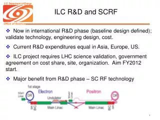
OUTLINE OF SCIPP ILC R&D PROGRAM • LSTFE Frint-End ASIC • Optimized for ILC (long ladders for barrel; high rates for forward tracking) • Applicable to both SiD and ILD • SiD KPIX/Double-Metal Development • SiD baseline; alternative to LSTFE • SCIPP has done group’s sensor testing, now beginning critical systems tests
OUTLINE (Continued) • Fundamental (“Generic”) R&D • Use of charge division for longitudinal coordinate (with Rich Partridge) • Solid-state noise sources • Prospects for RadHard Sensors (far-forward Calorimetry • If funded, will support SLAC collaboration • ESA test beam: SCIPP sensor expertise plus SLAC operation and dosimetry
OUTLINE (Continued) • SiD Simulation Projects • Tracking and momentum reconstruction validation • Non-prompt signatures
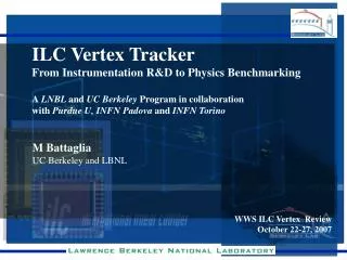
ILC Tracker Baseline Designs ILD Baseline: Si tracking envelops TPC; outer layers at 1.8m SiD Baseline: Five barrel and 4 endcap layers, to R = 125cm
The LSTFE ASIC Process: TSMC 0.25 m CMOS 1-3 s shaping time (LSTFE-I is ~1.2 s); analog measurement is Time-Over-Threshold
128 mip 1 mip Operating point threshold Readout threshold 1/4 mip High gain advantageous for overall performance (channel matching)
Li Hi Li+1 Hi+1 Li+2 Hi+2 Li+3 Hi+3 Li+4 Hi+4 Li+5 Hi+5 Li+6 Hi+6 Proposed LSTFE Back-End Architecture Low Comparator Leading-Edge-Enable Domain 8:1 Multi-plexing (clock = 50 ns) FIFO (Leading and trailing transitions) Event Time Clock Period = 400 nsec
Expected Observed RMS 1 meter Gaussian Fit LSTFE SPACE-POINT RESOLUTION 167 cm Ladder Observed noise vs. capacitive load (LSTFE-I) Simulated space-point resolution for “expected” noise
LSTFE-II Prototype Optimized for 80cm ladder (ILD barrel application) Institute “analog memory cells” to improve power-cycling switch-on from 30 msec to 1 msec Improved environmental isolation Additional amplification stage to improve S/N, control of shaping time, and channel-to-channel matching Improved control of return-to-baseline for < 4 mip signals (time-over-threshold resolution) 128 Channels (256 comparators) read out at 3 MHz, multiplexed onto 8 LVDS outputs Testing underway in SCIPP lab
The SiD KPIX/Double-Metal Baseline Design 10cm2 modules tessellate the five barrel tracking layers Traces on 2nd (surface) metal layer to two 1024-node bump-bonding arrays
SiD Double-Metal Sensor • SLAC/FNAL Design • Hamamatsu Fabrication • Testing at SCIPP
SiD Tiles: Biasing and Plane-to-Plane Capacitance Sensors bias at ~50 V. Capacitance shown is for all 1840 strips, but strips to backplane only For now: single sensor (sensor #26)
SiD Leakage Current (sensor #26): Average leakage for 1840 channels is about ~160 pA/channel • Next Steps: • Larger-scale testing (statistics) • Test of combined KPIX/Double-Metal perforamce to get underway at SCIPP this summer (pending DOE support)
Longitudinal Resolution via Charge Division Proposed by Rich Partridge, based on seminal paper by Radeka: V. Radeka "Signal, Noise and Resolution in Position-Sensitive Detectors", IEEE Trans. Nucl. Sci. 21, 51 (1974), which in turn references earlier work with planar sensors from R.B. Owen and M.L. Awcock, IEEE Trans. Nucl. Sci. 15, 290 (1968) Small ($16K) LCRD grant supports this work. Progress due to UCSC undergraduate physics major Jerome Carman Basic idea: For resistive sensor, impedances dominated by sensor rather than amplifier input impedance; charge should divide proportional to point of deposition. Read out implant (SLAC/FNAL “charge division” sensor has 600 k implant)
Charge Division Sensor Mock-Up 10-stage RC network PC board (Jerome Carman)
Charge Division Sensor Mock-Up Model 600 k resistive implant with 10-stage RC network Read out at both left (“L”) and right (“R”) ends Amplifiers: First Stage: TI OPA657 Low-noise FET OpAmp Later Stages: Analog Devices ADA4851 rail-to-rail video amp Measure Noise (either end): 0.64 fC
Mean Amplifier Response vs. Injection Point Right-Hand Amplifier P-Spice, including all parasitics Observed signal Fairly linear; little offset from 0 appropriate for charge division.
Longitudinal Resolution Estimate Trying to measure fractional distance f from right to left end of strip: Rewrite: Then, and dL, dR apparently uncorrelated.
Longitudinal Resolution Estimate: Conclusion • Depends upon location of hit (middle or near end of resistive implant) and the magnitude of the charge deposition. • Assume a 4 fC deposition in the middle of the strip (x=1): • However, note that , so this is not much better. • Optimize shaping time, implant resistivity, ? • Goal of better than 0.1 (1cm for SiD sensors).
Readout Noise for Linear Collider Applications • Use of silicon strip sensors at the ILC tend towards different limits than for hadron collider or astrophysical applications: • Long shaping time • Resistive strips (narrow and/or long) But must also achieve lowest possible noise to meet ILC resolution goals. How well do we understand Si strip readout noise?
Expected noise, assuming 75% reduction in strip noise Measured noise Strip Noise Idea: “Center Tapping” – half the capacitance, half the resistance? Result: no significant change in measured noise However, sensors have 237 m pitch Currently characterizing CDF L00 sensors
Parallel Resistance Series Resistance Amplifier Noise (parallel) Amplifier Noise (series) Standard Form for Readout Noise (Spieler) Fiand Fv are signal shape parameters that can be determined from average scope traces. There is some circumstantial evidence that this may be an oversimplification, particularly for the case of series noise…
CDF L00 Sensor “Snake” CDF L00 “Snake” LSTFE1 chip on Readout Board
CDF L00 Sensor “Snake” Plus much work eliminating environmental noise, constraining amplifier contributions…Thanks to Sean Crosby, UCSC undergraduate thesis student
Measured vs. Expected Noise “Rigorous Calc”: Carefully measured shape factors Fi, Fv. Johnson-Noise-Dominated for > 6 strips
Results rather surprising • Re-check methodology • Develop P-Spice simulation (as for charge-division studies Sean’s understudy, Kelsey Collier, will grab the reigns…
Conclusions SiD sensor: first pass characterization looks fine (complex design!). “Charge Division” sensors shorted by strips. LSTFE-2 awaits testing (soon!); design refined by studies of LSTFE-1 Charge division approach looks interesting; needs to be optimized and some questions explored (but what happens to S/N and transverse resolution?) Effects of series noise being questioned; empirical study of readout noise contributions underway Starting SPICE simulation of “snake” and charge-division setup to calibrate understanding (Ryan Stagg)
Radiation-Hard Silicon Sensors (SCIPP/SLAC) Far-Forward region: Need to tag electrons from two-photon events to remove SUSY backgrounds (to 20 mrad) Expected doses of 100s MRad anticipated for ILC running (5x limits for probed for ATLAS upgrade studies) UCSC experience with rad-hard sensors (e.g. Czochralski-process) and characterization, in combination with SLAC testbeams and dosimetry expertise Funding expected for studies in 2010-2011
Simulation Studies for the SiD Concept • Tracking Performance Evaluation • Reconstruction Efficiency • Momentum Resolution • Non-Prompt Tracks • Reconstruction Algorithms • GMSB Signatures
3-Hit Tracks & Non-Prompt Signatures Probably need 5+1 layers for prompt track If we require 4 hits for non-prompt tracks, sensitive region for kinked tracks is very limited.