Download
1 / 5
50 likes | 72 Vues
flexible pipe when buried, it is required that the pipe be more yielding than the embedment soil surrounding it.This is the source of flexible pipeu2019s external-load-carrying capacity. Under soil load, the pipe tends to deflect. The vertical diameter is compressed and the horizontal diameter expands by approximately the same amount in both directions When the horizontal diameter expands, it engages the passive resistance of the soil support at the<br>sides of the pipe. At the same time, the compression of the vertical diameter relieves the pipe of the major portion of the vertical soil load, which is then carried by the surrounding soil through the mechanism of an arching action over the pipe

E N D
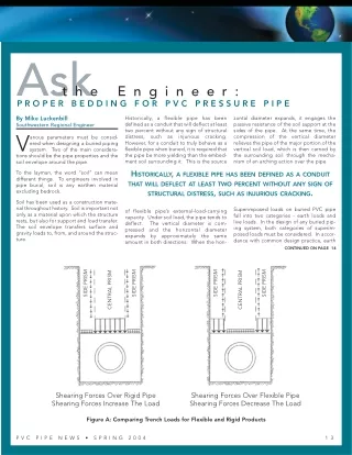
Ask P R O P E R B E D D I N G F O R P V C P R E S S U R E P I P E t h e E n g i n e e r : By Mike Luckenbill Southwestern Regional Engineer V tions should be the pipe properties and the soil envelope around the pipe. Historically, a flexible pipe has been defined as a conduit that will deflect at least two percent without any sign of structural distress, such as injurious cracking. However, for a conduit to truly behave as a flexible pipe when buried, it is required that the pipe be more yielding than the embed- ment soil surrounding it. This is the source zontal diameter expands, it engages the passive resistance of the soil support at the sides of the pipe. At the same time, the compression of the vertical diameter relieves the pipe of the major portion of the vertical soil load, which is then carried by the surrounding soil through the mecha- nism of an arching action over the pipe. arious parameters must be consid- ered when designing a buried piping system. Two of the main considera- HISTORICALLY, A FLEXIBLE PIPE HAS BEEN DEFINED AS A CONDUIT THAT WILL DEFLECT AT LEAST TWO PERCENT WITHOUT ANY SIGN OF STRUCTURAL DISTRESS, SUCH AS INJURIOUS CRACKING. To the layman, the word “soil” can mean different things. To engineers involved in pipe burial, soil is any earthen material excluding bedrock. Soil has been used as a construction mate- rial throughout history. Soil is important not only as a material upon which the structure rests, but also for support and load transfer. The soil envelope transfers surface and gravity loads to, from, and around the struc- ture. Superimposed loads on buried PVC pipe fall into two categories - earth loads and live loads. In the design of any buried pip- ing system, both categories of superim- posed loads must be considered. In accor- dance with common design practice, earth of flexible pipe’s external-load-carrying capacity. Under soil load, the pipe tends to deflect. The vertical diameter is com- pressed and the horizontal diameter expands by approximately the same amount in both directions. When the hori- CONTINUED ON PAGE 14 SIDE PRISM SIDE PRISM SIDE PRISM SIDE PRISM CENTRAL PRISM CENTRAL PRISM Shearing Forces Over Rigid Pipe Shearing Forces Increase The Load Shearing Forces Over Flexible Pipe Shearing Forces Decrease The Load Figure A: Comparing Trench Loads for Flexible and Rigid Products P V C P I P E N E W S • S P R I N G 2 0 0 4 1 3
EXCAVATED TRENCH WIDTH FINAL BACKFILL PIPE WIDTH COVER INITIAL BACKFILL PIPE EMBEDMENT PIPE ZONE SPRINGLINE PIPE HAUNCHING BEDDING FOUNDATION (MAY NOT BE REQUIRED) Figure B: Trench Embedment Terminology on earth loading technology for buried con- duits throughout the world is related, in buried pipe is modified by the response of the pipe and the relative movement of the CONTINUED FROM PAGE 13 loads and live loads are treated as separate design parameters. ALMOST ANY REASONABLE SOIL STRUCTURE WILL WORK FOR PVC PRESSURE PIPE BURIAL. The first solution to the problem of soil- induced loads on buried pipe was pub- lished by Professor Anson Marston at Iowa State University in 1913. Since then, the Marston Theory of Loads on Underground Conduits has been used in determining the loads on buried pipe. Much of the research part, to Marston's load theory. The basic concept of the theory is that the load due to the weight of the column of soil above a side columns of soil to the central column. When the side columns of soil between the pipe and the trench wall (pipe zone) are Table 1 Average Values Of Modulus Of Soil Reaction, E' (For Initial Flexible Pipe Deflection)* E' for Degree of Compaction of Haunching, in psi ASTM D2321 Dumped Slight Moderate 85% - 95% Proctor High Embedment Material Classification < 85% Proctor > 95% Proctor Manufactured Granular Angular Class I 1,000 3,000 3,000 3,000 Clean Sand & Gravel Class II 200 1,000 2,000 3,000 Sand & Gravel with Fines Class III 100 400 1,000 2,000 Silt & Clay Class IV 50 200 400 1,000 Organic Materials Class V No data available; consult a competent soils engineer; otherwise use E’ = 0 * A more detailed table is available for download from Uni-Bell’s website, www.uni-bell.org. The table is in Uni-Bell’s technical report “Deflection: The Pipe/Soil Mechanism,” UNI-TR-1. 1 4 P V C P I P E N E W S • S P R I N G 2 0 0 4
more compressible than the pipe, this causes the pipe to assume load generated across the width of the trench. This is typically the case for rigid prod- ucts like concrete and clay. However, when pipe has the ability to deflect without cracking, this produces a situation that allows the central prism of soil (directly over the pipe) to settle more in relation to the adjacent soil columns (between the pipe and the trench wall). This settlement produces shearing forces which reduce the load on a flexible pipe to an amount less than the weight of the prism directly over it. The two scenarios are shown in Figure A on page 13. Regardless of pipe stiffness, as soil in the trench settles or moves downward compared to the trench sidewall, friction forces are generated which act to reduce the weight of the trench-wide soil col- umn. Marston's Load Theory predicts and accounts for these frictional shearing forces. BEDDING ANGLE BEDDING VALUES OF BEDDING CONSTANT ,K BEDDING ANGLE K 0° 0.110 30° 0.108 Figure B on page 14 shows a typical trench cross- section denoting standard nomenclature used in the plastic pipe industry. The word “bedding” is gener- ally accepted as the soil structure around the pipe and not necessarily the bedding upon which the pipe rests. This would include the haunching and initial backfill areas. The soil structure requirements for pressure pipe are less stringent than for gravity sewer pipe. This is primarily due to the fact that pressure pipe is usually buried at shallow depths. Also, pressure pipes tend to have thicker walls than 45° 0.105 60° 0.102 90° 0.096 120° 0.090 180° 0.083 Figure C: Bedding Angle Defined CONTINUED ON PAGE 16 Table 2 Calculated Deflections Of Buried PVC Pressure Pipe; Deflection (percent) For Prism, Highway H20, or Railway E80 Loads 2’ H20 4’ H20 6’ H20 DR 14 0.51 0.48 0.44 0.35 0.26 DR 18 1.11 0.96 0.81 0.55 0.36 DR 21 1.76 1.40 1.11 0.68 0.41 DR 25 2.86 2.03 1.46 0.80 0.45 DR 26 3.18 2.18 1.54 0.82 0.46 8’ H20 10’ H20 Height of Cover Live Load E’ Value 50 200 400 1000 2000 E’ Value 50 200 400 1000 2000 E’ Value 50 200 400 1000 2000 E’ Value 50 200 400 1000 2000 E’ Value 50 200 400 1000 2000 Prism E80 Prism E80 Prism E80 Prism E80 Prism E80 0.13 0.12 0.11 0.09 0.07 0.58 0.54 0.50 0.40 0.30 2.25 2.10 1.92 1.54 1.15 0.27 0.25 0.23 0.18 0.14 0.49 0.46 0.42 0.34 0.25 1.75 1.63 1.49 1.19 0.89 0.40 0.37 0.34 0.27 0.21 1.66 1.54 1.42 1.13 0.85 0.54 0.50 0.46 0.37 0.27 0.59 0.55 0.50 0.40 0.30 1.43 1.33 1.22 0.97 0.73 0.67 0.62 0.57 0.46 0.34 0.67 0.62 0.57 0.46 0.34 1.28 1.20 1.10 0.88 0.66 0.29 0.25 0.21 0.14 0.09 1.26 1.09 0.92 0.63 0.41 4.89 4.22 3.57 2.43 1.59 0.58 0.50 0.42 0.29 0.19 1.07 0.92 0.78 0.53 0.35 3.79 3.27 2.76 1.89 1.23 0.87 0.75 0.64 0.43 0.28 3.60 3.10 2.62 1.79 1.17 1.16 1.00 0.85 0.58 0.38 1.28 1.11 0.94 0.64 0.42 3.10 2.67 2.26 1.54 1.01 1.45 1.25 1.06 0.72 0.47 1.45 1.25 1.06 0.72 0.47 2.79 2.40 2.03 1.39 0.91 0.46 0.37 0.29 0.18 0.11 1.99 1.59 1.25 0.77 0.47 7.71 6.16 4.86 2.97 1.81 0.92 0.73 0.58 0.35 0.21 1.68 1.34 1.06 0.65 0.39 5.97 4.77 3.76 2.30 1.40 1.37 1.10 0.87 0.53 0.32 5.67 4.53 3.57 2.19 1.33 1.83 1.46 1.15 0.71 0.43 2.02 1.62 1.27 0.78 0.47 4.89 3.90 3.08 1.88 1.14 2.29 1.83 1.44 0.88 0.54 2.29 1.83 1.44 0.88 0.54 4.39 3.51 2.77 1.69 1.03 0.75 0.53 0.38 0.21 0.12 3.23 2.29 1.65 0.90 0.51 12.56 8.91 6.42 3.49 1.99 1.49 1.06 0.76 0.42 0.24 2.74 1.94 1.40 0.76 0.43 9.73 6.90 4.97 2.71 1.54 2.24 1.59 1.14 0.62 0.35 9.23 6.55 4.72 2.57 1.46 2.98 2.12 1.53 0.83 0.47 3.29 2.34 1.68 0.92 0.52 7.96 5.65 4.07 2.21 1.26 3.73 2.65 1.91 1.04 0.59 3.73 2.65 1.91 1.04 0.59 7.15 5.07 3.66 1.99 1.13 0.83 0.57 0.40 0.21 0.12 3.59 2.47 1.74 0.93 0.52 13.95 9.59 6.77 3.59 2.02 1.66 1.14 0.80 0.43 0.24 3.04 2.09 1.47 0.78 0.44 10.80 7.43 5.24 2.78 1.56 2.49 1.71 1.21 0.64 0.36 10.26 7.05 4.98 2.64 1.48 3.31 2.28 1.61 0.85 0.48 3.66 2.51 1.77 0.94 0.53 8.84 6.07 4.29 2.28 1.28 4.14 2.85 2.01 1.07 0.60 4.14 2.85 2.01 1.07 0.60 7.94 5.46 3.85 2.05 1.15 P V C P I P E N E W S • S P R I N G 2 0 0 4 1 5
CONTINUED FROM PAGE 15 a comparable gravity pipe in order to han- dle the pressure capacity typically speci- fied. This often results in external load capabilities that far exceed the design requirement. As a consequence, almost any reasonable soil structure will work for PVC pressure pipe burial. symbolically represented as E’. The aver- age values are shown in Table 1 on page 14. This variable is very important in flexible becomes increasingly important as depth of cover increases. However, at relatively shallow depths in the 3 to 10 foot range E’ THE STRENGTH AND SUITABILITY OF THE PVC PIPE FOR BURIAL MADE IT EQUAL TO (OR BETTER THAN) OTHER TRADITIONAL PIPING MATERIALS... The “bedding factor” is also used in burial equations. Precise values are shown in Figure C on page 15. The bedding factor has little effect on results of burial calcula- tions and is usually taken as 0.100. pipe burial calculations. E’ in the haunch area is a measure of the ability of the soil to absorb live and dead loads transmitted through the pipe as it deflects over time. E’ values of 700 to 2,000 psi will cover almost any burial situation as long as there is full support in the haunches of the pipe. What is the modulus of soil reaction? It is CONTINUED ON PAGE 18 Table 2 (cont.) Calculated Deflections Of Buried PVC Pressure Pipe; Deflection (percent) For Prism, Highway H20, or Railway E80 Loads 2’ H20 4’ H20 6’ H20 8’ H20 10’ H20 Height of Cover Live Load E’ Value 50 200 400 1000 2000 E’ Value 50 200 400 1000 2000 E’ Value 50 200 400 1000 2000 Prism E80 Prism E80 Prism E80 Prism E80 Prism E80 DR 32.5 5.52 3.08 1.94 0.92 0.49 DR 41 8.85 3.90 2.24 0.98 0.51 DR 51 12.33 4.46 2.41 1.01 0.51 1.44 0.80 0.51 0.24 0.13 6.24 3.49 2.19 1.04 0.55 24.22 13.53 8.52 4.04 2.15 2.88 1.61 1.01 0.48 0.26 5.28 2.95 1.86 0.88 0.47 18.77 10.48 6.60 3.13 1.66 4.32 2.41 1.52 0.72 0.38 17.81 9.95 6.26 2.97 1.58 5.76 3.22 2.02 0.96 0.51 6.35 3.55 2.23 1.06 0.56 15.35 8.57 5.40 2.56 1.36 7.20 4.02 2.53 1.20 0.64 7.20 4.02 2.53 1.20 0.64 13.79 7.70 4.85 2.30 1.22 2.31 1.02 0.58 0.26 0.13 10.01 4.42 2.53 1.11 0.57 38.88 17.14 9.82 4.31 2.22 4.62 2.04 1.17 0.51 0.28 8.47 3.74 2.14 0.94 0.48 30.12 13.28 7.61 3.34 1.72 6.93 3.05 1.75 0.77 0.40 28.59 12.60 7.22 3.17 1.64 9.24 4.07 2.33 1.02 0.53 10.19 4.49 2.58 1.13 0.58 24.63 10.86 6.22 2.73 1.41 11.55 5.09 2.92 1.28 0.66 11.55 5.09 2.92 1.28 0.66 22.13 9.76 5.59 2.45 1.27 3.22 1.16 0.63 0.26 0.13 13.94 5.04 2.72 1.14 0.58 54.13 19.57 10.57 4.44 2.26 6.43 2.33 1.26 0.53 0.27 11.79 4.27 2.30 0.97 0.49 41.93 15.16 8.19 3.44 1.75 9.65 3.49 1.88 0.79 0.40 39.80 14.39 7.78 3.27 1.66 12.86 4.65 2.51 1.06 0.54 14.19 5.13 2.77 1.17 0.59 34.30 12.40 6.70 2.82 1.43 16.08 5.81 3.14 1.32 0.67 16.08 5.81 3.14 1.32 0.67 30.82 11.14 6.02 2.53 1.29 12’ H20 14’ H20 16’ H20 DR 14 1.07 1.00 0.91 0.73 0.55 DR 18 2.33 2.01 1.69 1.16 0.76 DR 21 3.66 2.93 2.31 1.41 0.86 DR 25 5.97 4.23 3.05 1.66 0.94 18’ H20 20’ H20 Height of Cover Live Load E’ Value 50 200 400 1000 2000 E’ Value 50 200 400 1000 2000 E’ Value 50 200 400 1000 2000 E’ Value 50 200 400 1000 2000 Prism E80 Prism E80 Prism E80 Prism E80 Prism E80 0.80 0.75 0.69 0.55 0.41 0.80 0.75 0.69 0.55 0.41 1.25 1.16 1.07 0.85 0.64 0.94 0.87 0.80 0.64 0.48 0.94 0.87 0.80 0.64 0.48 1.27 1.19 1.09 0.87 0.65 1.07 1.00 0.91 0.73 0.55 1.35 1.26 1.15 0.92 0.69 1.21 1.12 1.03 0.82 0.62 1.21 1.12 1.03 0.82 0.62 1.43 1.33 1.22 0.97 0.73 1.34 1.25 1.14 0.91 0.68 1.34 1.25 1.14 0.91 0.68 1.51 1.40 1.29 1.03 0.77 1.74 1.50 1.27 0.87 0.57 1.74 1.50 1.27 0.87 0.57 2.71 2.34 1.98 1.35 0.88 2.04 1.75 1.48 1.01 0.66 2.04 1.75 1.48 1.01 0.66 2.76 2.38 2.01 1.37 0.90 2.33 2.01 1.69 1.16 0.76 2.93 2.53 2.14 1.46 0.95 2.62 2.26 1.91 1.30 0.85 2.62 2.26 1.91 1.30 0.85 3.10 2.67 2.26 1.54 1.01 2.91 2.51 2.12 1.45 0.95 2.91 2.51 2.12 1.45 0.95 3.27 2.82 2.38 1.63 1.06 2.75 2.20 1.73 1.06 0.64 2.75 2.20 1.73 1.06 0.64 4.28 3.42 2.70 1.65 1.00 3.21 2.56 2.02 1.24 0.75 3.21 2.56 2.02 1.24 0.75 4.35 3.48 2.74 1.68 1.02 3.66 2.93 2.31 1.41 0.86 4.62 3.69 2.91 1.78 1.08 4.12 3.29 2.60 1.59 0.97 4.12 3.29 2.60 1.59 0.97 4.89 3.90 3.08 1.88 1.14 4.58 3.66 2.89 1.77 1.07 4.58 3.66 2.89 1.77 1.07 5.15 4.12 3.25 1.99 1.21 4.48 3.18 2.29 1.25 0.71 4.48 3.18 2.29 1.25 0.71 6.97 4.94 3.56 1.94 1.10 5.22 3.70 2.67 1.45 0.83 5.22 3.70 2.67 1.45 0.83 7.09 5.03 3.62 1.97 1.12 5.97 4.23 3.05 1.66 0.94 7.52 5.34 3.85 2.09 1.19 6.71 4.76 3.43 1.87 1.06 6.71 4.76 3.43 1.87 1.06 7.96 5.65 4.07 2.21 1.26 7.46 5.29 3.81 2.08 1.18 7.46 5.29 3.81 2.08 1.18 8.39 5.95 4.29 2.33 1.33 1 6 P V C P I P E N E W S • S P R I N G 2 0 0 4
Type 2 Type 1 Type 4 Type 3 Flat-bottom trench.* Embedment lightly consolidated to centerline of pipe. Flat-bottom trench.* Loose embedment. Pipe bedded on 4 in. (100 mm) minimum of loose soil.† Embedment lightly consolidated to top of pipe. Pipe bedded on sand, gravel, or crushed stone to depth of 1/8 pipe diameter, 4 in. (100mm) minimum. Embedment compacted to top of pipe. (Approximately 80 percent Standard Proctor, AASHTO T-99 or ASTM D 698.) E’ = 1,000 psi (6,900 kPa), K = 0.096 E’ = 50 psi (340 kPa), K = 0.110 E’ = 200 psi (1,380 kPa), K = 0.110 E’ = 400 psi (2,760 kPa), K = 0.102 Figure D Notation Type 5 NOTE: Required embedment type will depend on the pipe’s dimension ratio, internal operating pressure, and external load, and shall be specified by the purchaser. (see Sec. 5.3) * “Flat-bottom is defined as undisturbed earth. † “Loose soil” or “select material” is defined as native soil excavated from the trench, free of rocks, foreign materials, and frozen earth. A soft “loose soil” bedding will contour to the pipe bottom. Caution must be excercised to ensure proper placement of embedment material under the haunches of the pipe. Pipe embedded in compacted granular material to centerline of pipe. Compacted granular or select material† to top of pipe. (Approximately 90 percent Standard Proctor, AASHTO T-99 or ASTM D 698) E’ = 2,000 psi (13,800 kPa), K = 0.083 Figure D: Typical Trench Types in the PVC Installation Standard, AWWA C605 Type 2 Type 1 Type 4 Type 3 Flat-bottom trench.† Backfill lightly consolidated to centerline of pipe. Flat-bottom trench.† Loose backfill. Pipe bedded on 4 in. (100 mm) minimum of loose soil.‡ Backfill lightly consolidated to top of pipe. Pipe bedded on sand, gravel, or crushed stone to depth of 1/8 pipe diameter, 4 in. (100mm) minimum. Backfill compacted to top of pipe. (Approximately 80 percent Standard Proctor, AASHTO T-99.) Figure E Notation Type 5 * For 14-in. (355-mm) and larger pipe, consideration should be given to the use of laying conditions other than type 1. † “Flat-bottom is defined as undisturbed earth. ‡ “Loose soil” or “select material” is defined as native soil excavated from the trench, free of rocks, foreign materials, and frozen earth. A soft “loose soil” bedding will contour to the pipe bottom. Caution must be excercised to ensure proper placement of embedment material under the haunches of the pipe. Pipe embedded in compacted granular material to centerline of pipe. Compacted granular or select material‡ to top of pipe. (Approximately 90 percent Standard Proctor, AASHTO T-99.) Figure E: Typical Trench Types in the Ductile Iron Installation Standard, AWWA C600 P V C P I P E N E W S • S P R I N G 2 0 0 4 1 7