Download
1 / 3
30 likes | 31 Vues
detection programs are not necessary in the sectors where the water distribution lines are constructed with PVC pipes. u201cThis fact allows<br>us to concentrate our limited resources where they are most needed, in the sectors built with iron pipe,u201d states Mr. Perreault, who points out that flushing is also a thing of the past for the PVC sectors.

E N D
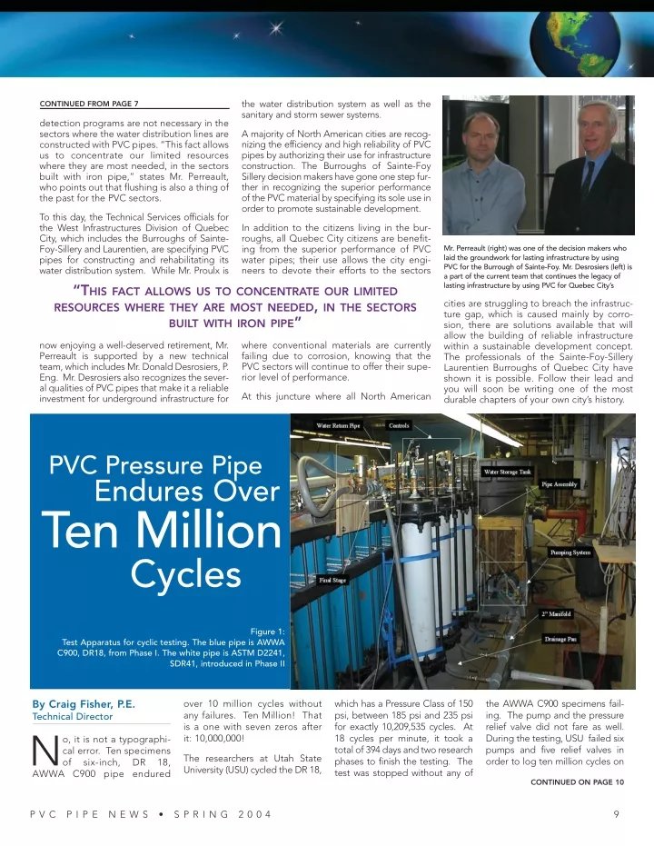
the water distribution system as well as the sanitary and storm sewer systems. CONTINUED FROM PAGE 7 detection programs are not necessary in the sectors where the water distribution lines are constructed with PVC pipes. “This fact allows us to concentrate our limited resources where they are most needed, in the sectors built with iron pipe,” states Mr. Perreault, who points out that flushing is also a thing of the past for the PVC sectors. A majority of North American cities are recog- nizing the efficiency and high reliability of PVC pipes by authorizing their use for infrastructure construction. The Burroughs of Sainte-Foy Sillery decision makers have gone one step fur- ther in recognizing the superior performance of the PVC material by specifying its sole use in order to promote sustainable development. To this day, the Technical Services officials for the West Infrastructures Division of Quebec City, which includes the Burroughs of Sainte- Foy-Sillery and Laurentien, are specifying PVC pipes for constructing and rehabilitating its water distribution system. While Mr. Proulx is “THIS FACT ALLOWS US TO CONCENTRATE OUR LIMITED RESOURCES WHERE THEY ARE MOST NEEDED, IN THE SECTORS BUILT WITH IRON PIPE” In addition to the citizens living in the bur- roughs, all Quebec City citizens are benefit- ing from the superior performance of PVC water pipes; their use allows the city engi- neers to devote their efforts to the sectors Mr. Perreault (right) was one of the decision makers who laid the groundwork for lasting infrastructure by using PVC for the Burrough of Sainte-Foy. Mr. Desrosiers (left) is a part of the current team that continues the legacy of lasting infrastructure by using PVC for Quebec City’s cities are struggling to breach the infrastruc- ture gap, which is caused mainly by corro- sion, there are solutions available that will allow the building of reliable infrastructure within a sustainable development concept. The professionals of the Sainte-Foy-Sillery Laurentien Burroughs of Quebec City have shown it is possible. Follow their lead and you will soon be writing one of the most durable chapters of your own city’s history. where conventional materials are currently failing due to corrosion, knowing that the PVC sectors will continue to offer their supe- rior level of performance. now enjoying a well-deserved retirement, Mr. Perreault is supported by a new technical team, which includes Mr. Donald Desrosiers, P. Eng. Mr. Desrosiers also recognizes the sever- al qualities of PVC pipes that make it a reliable investment for underground infrastructure for At this juncture where all North American PVC Pressure Pipe Endures Over Ten Million Cycles Figure 1: Test Apparatus for cyclic testing. The blue pipe is AWWA C900, DR18, from Phase I. The white pipe is ASTM D2241, SDR41, introduced in Phase II By Craig Fisher, P.E. Technical Director N AWWA C900 pipe endured over 10 million cycles without any failures. Ten Million! That is a one with seven zeros after it: 10,000,000! which has a Pressure Class of 150 psi, between 185 psi and 235 psi for exactly 10,209,535 cycles. At 18 cycles per minute, it took a total of 394 days and two research phases to finish the testing. The test was stopped without any of the AWWA C900 specimens fail- ing. The pump and the pressure relief valve did not fare as well. During the testing, USU failed six pumps and five relief valves in order to log ten million cycles on o, it is not a typographi- cal error. Ten specimens of six-inch, The researchers at Utah State University (USU) cycled the DR 18, DR 18, CONTINUED ON PAGE 10 P V C P I P E N E W S • S P R I N G 2 0 0 4 9
TABLE 1. TEST PRESSURES AND STRESSES Test Specimen Description Minimum Pressure Maximum Pressure Mean Stress Stress Amplitude (psi) (psi) (psi) (psi) One DR 18, AWWA C900, PC 150 psi 185 235 1787 213 Two SDR 41, ASTM D2241, PR 100 psi 82 123 2000 400 Three SDR 41, ASTM D2241, PR 100 psi 0 154 1500 1500 Four SDR 41, ASTM D2241, PR 100 psi 56.5 149 2000 900 Uni-Bell first contracted with USU in 1999 to re-evaluate the cyclic capabilities of PVC pres- sure pipe. At the time, there were two competing theories. edition of The Handbook of PVC Pipe: Design and Construction shows Vinson’s theory.) The Europeans had a competing the- ory that stated the cyclic life was lished his finding in February of 2001. That testing showed that the cyclic life of PVC was a func- tion of two variables - not one. PVC pipe fatigue is a function of both the mean stress and the stress amplitude. (The fourth edition of the Handbook, pub- lished in August of 2001, shows Moser’s 2001 theory.) CONTINUED FROM PAGE 9 the PVC pipe. The test set-up is shown in Figure 1 on page 9. The blue pipe is the AWWA C900 pipe, and the white pipe is six- inch, SDR 41, ASTM D2241 pipe. DURING THE TESTING, UTAH STATE UNIVERSITY FAILED SIX PUMPS AND FIVE RELIEF VALVES IN ORDER TO LOG TEN MILLION CYCLES ON THE PVC PIPE. This testing was a part of Phase II of USU’s research project on the cyclic capabilities of PVC pres- sure pipe. In the Spring 2001 edition of the PVC News, we reported on the research results from Phase I and said that more data points would be collected. Well the data is in, and the results are impressive. Phase I The first phase involved only AWWA C900 pipe. As mentioned earlier, this pipe was cycled from 185 psi to 235 psi, which resulted in an average stress of 1,787 psi and a stress amplitude of 213 psi. Vinson’s formula predicted failure at 322,000 cycles. After success- fully logging 3.5 million cycles, the first phase of testing was conclud- ed and a new cyclic theory for PVC was published. However, Dr. Moser stated that more data points were needed in order to fine-tune the design chart that he developed. The first theory was developed by Vinson and stated that the cyclic life of PVC was a function of peak stress only. (The third a function of only the stress amplitude. Dr. Moser complet- ed the first phase of the testing in the summer of 2000 and pub- Background Stress Amplitude (psi) Phase II So in April of 2001, Uni-Bell entered its second contract on this project with USU in order to continue the work begun in Phase I. This time, ASTM D2241 PVC pipe would be subjected to pressures and amplitudes well beyond that recommended in the design standards. Also, the testing on the AWWA C900 pipe would be re-started. SDR 41, ASTM D2241 pipe, with a Pressure Rating of 100 psi, was selected for the abusive cyclic Number of Cycles Figure 3: New cyclic design chart updated after collecting extra data points from the second phase of testing. CONTINUED ON PAGE 19 1 0 P V C P I P E N E W S • S P R I N G 2 0 0 4
The How-To Handbook of PVC Pipe 522 PAGES The only complete reference for those who plan, design, install and operate PVC sys- tems for municipal water mains, sanitary sewer and storm water drainage systems. If you are planning, or now operate a PVC pressure or non-pressure system, this handbook is a must! O N L Y $ 4 0 P E R C O P Y (Includes postage and handling for US and Canadian orders.) Payable in US Funds, Texas Residents add 8.25 percent sales tax. Figure 2: The cyclic pressures applied during testing followed a sawtooth pattern. Plus air mail charges: ❑ All Other Countries $28/bk CONTINUED FROM PAGE 10 ❑ Mexico $16/bk pressure combinations. Using pipe with a higher dimension ratio allowed higher stresses to be generated in the pipe wall at lower pressures. Generating the same stresses in DR 18 would require a prohibitively expensive pumping system. Also, the researchers learned in Phase I to expect equipment failures. The extreme pressures take their toll on the equip- ment, and so, replacement pumps were a large part of the equipment cost in the research budget. Mail coupon with your check to: Uni-Bell PVC Pipe Association 2655 Villa Creek Drive, Suite 155 Dallas, Texas 75234 Indicate preferred format: ❑ Hard-Bound ❑ CD-ROM PC Requirements for Electronic Version: Table 1 on page 10 shows the average pressure and amplitude for the four pressure combinations. The corre- sponding wall stresses are also listed. • I386, I486, Pentium or Pentium Pro processor-based personal computer • Microsoft Windows 95 or Windows NT 3.51 or later • 8 MB of RAM (16 MB for Windows NT) available to Acrobat Reader • 10 MB of available hard disk space • CD-ROM drive The pattern of cyclic pressure applied was a sawtooth. The computer screen in Figure 2 (above) displays the pressure wave applied. The minimum and maximum pres- sures on Test One were regulated to within +/- 5 psi. A more accurate control system was used on Test Two, Three, and Four. Pressures were regulated to within +/- 3 psi. Temperature was 22°C +/- 2 (71.6°F +/- 3.6). Macintosh Requirements for Electronic Version: • 68020 or greater processor or Power Macintosh • 3.5 MB of RAM (5 MB for Power Macintosh) available to Acrobat Reader • Apple system software version 7.0 or later • CD-ROM drive Cyclic Design Graph With the help of the new data points, a fine-tuned design graph is now available. It appears in Figure 3 on page 10. Name ____________________________________________________ Company __________________________________________________ Address __________________________________________________ City ______________________________________________________ State/Province ______________________________________________ Zip/Postal Code ____________________________________________ Country____________________________________________________ Phone: ____________________________________________________ Fax: ______________________________________________________ E-mail: ____________________________________________________ L------------------------J The chart is a wonderful design tool for engineers involved in turf irrigation or sewer force main design. Those types of systems sometimes see surges of greater magnitude with greater frequency. We plan a follow-up article that provides a cyclic design example for a force main system. P V C P I P E N E W S • S P R I N G 2 0 0 4 1 9