Digital Control Systems
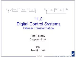
Digital Control Systems. z - Plane Analysis of Discrete Time Control Systems. Digital Control System.

Digital Control Systems
E N D
Presentation Transcript
Digital Control Systems z-Plane Analysis of Discrete Time Control Systems
Digital Control System A control system which uses a digital computer as a controller or compensator is knownas digital control system. The advantages of using a digital computers for compensationinclude: accuracy, reliability, economy and most importantly, flexibility.
Sampler Convertsan anolog signal to a digital signal (train of pulses) A practical sampler acts like a switch closing every T seconds for a short duration ofp seconds. Therefore, sampled signal can represented as follows: The output of an ideal sampler is given by (u(t) is unit step function)
Sampler • In practice pis much smaller and can be neglected.This leads to the Ideal Sampler. • The Ideal Sampling process can be considered as the multiplication ofa pulse train with a continuous signal Signalr(t) after samling Signal r(t) after ideal samling r* (t) = P(t) r(t)
Sampler r(t) = 0, for t < 0
Hold Device The function of hold device is to convert sampled signal into continuous signal. Thevalues of continuous time signal in between the sampling instants are calculated byextrapolation. The continuous signal h(t) during the time interval t may be approximatedby a polynomial in: Since the continuous time output signal, at sampling instants,must equal input signal, : Therefore: 0 The hold device is called n-th order hold if it uses an n-th order polynomial extrapolator. n=1 firstorderhold n=0 zeroorderhold
Hold Device Zero OrderHold (ZOH) Input-Outputsignalsfor a ZOH The output of ZOH:
Hold Device Zero OrderHold (ZOH) The output of ZOH: We know from Laplace transforms that ZOH Transfer function
Hold Device Zero OrderHold (ZOH) Suppose the transfer function G(s) follows the ZOH. Then the product of ZOH and G(s) becomes: Obtainthe z transform of X(s): Let
Hold Device Zero OrderHold (ZOH)
Hold Device Zero OrderHold (ZOH) Example:The response of a sampler and a ZOH to a ramp input for two different values of a sampling period. A sampler and ZOH can accurately follow the input signal if thesampling time T is small compares to the transient changes in thesignal Example: Ideal sampler followed by a ZOH
Pulse Transfer Function Transferfunction of a continuous time system relates the Laplace transformof the continuous-time output to that of the continuous time input. Pulse transferfunction relates the z-transform of the output at the sampling instants to that of thesampledinput. StarredLaplaceTransform Assumption: Zeroinitial conditions. • Whiletaking the starred Laplace tranform of a product of transforms, wheresome are ordinary Laplace transforms and others are starred Laplace transform, thefunctions already in starred Laplace transforms can be factored out of the starredLaplacetransform. • The output of a sampled-data system is continuous withrespect to time. However the pulse transform (starred LT) of the output, Y (s) and z-transformof the output Y (z), gives the values of output y(t) only at sampling instants.
Pulse Transfer Function StarredLaplaceTransform Since the z transform is starred Laplace transform with esTreplaced by z,
Pulse Transfer Function StarredLaplaceTransform The presence orabsence of theinputsampler is crucial in determiningthepulse transfer function of a system Example:
Pulse Transfer Function Pulse transfer function of cascaded elements Taking starred Laplace transforms on both sides of above equations
Pulse Transfer Function Pulse transfer function of cascaded elements where
Pulse Transfer Function Pulse transfer function of closedloopsystems
Pulse Transfer Function Example:
Pulse Transfer Function Pulse transfer function of a digitalcontroller Pulse tranfer function of a digital controller can be easily obtained from its input-ouputcharacteristic which is specified by means of difference equation: where m(k) and e(k) are the output and input signals respectively. Taking z-transformsand simplifying we get the pulse transfer function of the digital controller:
Pulse Transfer Function Closed-loop Pulse transfer function of a digital control system Ageneral block diagram of a digital control system Mathematicalblock diagram of a digitalcontrolsystem
Pulse Transfer Function Closed-loop Pulse transfer function of a digital control system
Realization of DigitalControllersandDigitalFilters The general form of thepulse transfer functionbetweentheoutput Y(z) and X(z) is givenby • Direct programming • Standart programming Intheseprogrammings, coefficientsappear as multipliers in theblockdiagramrealization. Thoseblockdiagramschemeswherethecoefficientsappeardirectly as multipliersarecalleddirectstructures.
Realization of DigitalControllersandDigitalFilters Direct programming Realizethenumeratoranddenominator of thepulse transfer functionusingseparatesets of delayelements. Total number of delay elementsin directprogramming=n+m Digitalfilter: Blockdiagramrealization:
Realization of DigitalControllersandDigitalFilters Standart programming Thenumber of delayelementsrequired in directprogramming can be reduced. Thenumber of delayelementsused in realizingthepulse transfer function can be reducedfromn+mto n (wheren≥m) byrearrangingtheblockdiagram.
Realization of DigitalControllersandDigitalFilters Standart programming