Download
1 / 13
130 likes | 309 Vues
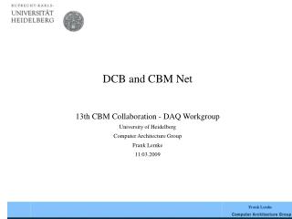
DCB and CBM Net 13th CBM Collaboration - DAQ Workgroup University of Heidelberg Computer Architecture Group Frank Lemke 11.03.2009. Outline. Data Combiner Board Functionality and Status CBM Net Overview Protocol Features and Implementation Current Status Conclusion & Outlook.

E N D
DCB and CBM Net 13th CBM Collaboration - DAQ Workgroup University of Heidelberg Computer Architecture Group Frank Lemke 11.03.2009
Outline • Data Combiner Board Functionality and Status • CBM Net Overview • Protocol Features and Implementation • Current Status • Conclusion & Outlook
DCB Functionality • HTX Connector with 16bit LVDS bidirectional interface • FPGA Virtex-4 FX60 or FX100 speed grade -10,-11 or -12 • 6 SFPs • 128MByte of DDR2 DRAM (optional 512MByte) • 512 Mb of user FLASH, 16bit interface to FPGA • 125MHz low jitter clock oscillator • Power supply with only 12V and 3.3V from HTX connector • Power consumption of 6 to 24W
DCB Status • DCB is completely tested • DCB is in use at our lab for prototyping research • DCB is successfully in use by many partners at universitiesand in industry • The newest external project with integrated DCB for communicationis a 64 nodes research cluster in Valencia (1024 Processors) • Bug fixes and optimizations from V 1.0 to V 1.2 • Additional options for CBM Net included in V1.3
ROC FEE … ABB DCB FEE ROC FEE FEE CBM Net – Prototype Structure Specific communication protocol for CBM usage: • Guarantee for Deterministic Latency Messages (DLM) • High data bandwidth for data streamROC => ABB • High reliability for control messagesABB => ROC • Fault detection and fault tolerance Administration Packets Slow Control Data flow ROC = Readout Controller DCB = Data Combiner Board ABB = Active Buffer Board
Message Types • Data Packet • Data messages with CRC • Only with error detection • Slow Control Packet • Control messages with CRC • Retransmission on error • Administration Characters • 1-Bit error correction • IDLE, INIT, ACK, NACK … • Deterministic latency message (DLM)
16 Bit 8 – 64 Byte 16 Bit 16 Bit SOP DATA CRC EOP Protocol Implementation • 16 Bit alignment at 125 MHz • Hamming distance for control signals • Standard initialization sequence measures fixed latency • DLM needs a well defined coding as a control signal with Hamming distance of 3 for a 1-Bit error correction • Different virtual channels for each message type Example packet structure of a data packet:
Protocol Features • Forward error correction of 1-Bit for all special characters • Meets required hierarchical structure for CBM Net • Optimized data bandwidth 91.428 % ( 73.148 % with 8b/10b) • Fast and efficient administration packets • Well defined Deterministic Latency Messages for synchronization and special purposes • Retransmission for Control Packets • Different virtual channels for each message type
Specialties in the DLM Implementation The guarantee for deterministic Latency lead to Problems: • Receive clock has to be used for sending =>Implementation of Jitter cleaner extension for DCB • Specific MGT and GTP configuration to get always the same delay after initialization • Special virtual channel in the Verilog implementation including Priority Request Insertion System source clock vs. recovered clock
Current Status • Basic Communication tested between: • DCB – DCB • DCB – ROC • ABB – DCB • Deterministic Latency for MGTs and GTPs proved with new designs • All existing coded parts are directly implemented in a clean modular way for reusability in later design phases • First version of Protocol implemented in Verilog • Test setup for first protocol version is in preparation => Next step is the first hierarchical communication test with CBM protocol
Demonstrator I ROC = Readout Controller DCB = Data Combiner Board ABB = Active Buffer Board * Thanks to Walter F.J. Mueller for this picture.
Conclusion & Outlook • Setup and Test of hierarchical implementation in diverse steps towards the Demonstrator I. • Iterative improvement of CBM protocol and the attached system components towards the Demonstrator I. • Collect data from Demonstrator I for future implementations needs. • Complete system simulations should be done=> the ability to decide • System structure • Network type and hierarchy • Read-Out buffer features and dimensions • Data and memory organization => Build next Generation prototype
Thank you for your attention ! Questions ?