Download
1 / 45
450 likes | 572 Vues
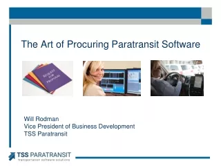
High Accuracy Helicopter Lidar & Mapping Jeffrey B. Stroub, CP,RLS,PPS,SP Vice President Business Development September 9, 2014. Understanding USGS LiDAR Base Specification Version 1.0. Jeff Stroub CP, RLS, PPS, SP Vice-President Business Development September 16, 2014.

E N D
High Accuracy Helicopter Lidar & MappingJeffrey B. Stroub, CP,RLS,PPS,SPVice President Business Development September 9, 2014 Understanding USGS LiDAR Base Specification Version 1.0 Jeff Stroub CP, RLS, PPS, SP Vice-President Business Development September 16, 2014
Goal USGS Base Specification • Consistency – all USGS funded LiDAR Collections • USGS Interest is only LiDAR Derived Elevation Models • USGS Scope specific to their mission • Hydro-Flattened surface • Hydro Enforced optional surface • A carefully planned project may support other uses • USGS Version 1.1 in concept stage
H. Karl Heidemann, GISP Physical Scientist U.S. Geological Survey/EROS
Background • In response to ARRA funding for USGS LiDAR collection, development of a common minimum specification was begun in early 2009; the USGS NGP Lidar Base Specification, Version 1.0 was published in the summer 2012: . • Time marches on … • NEEA Study on national LiDAR value published • The 3DEP established • ASPRS Accuracy Standards developed • Technical advances in the industry • The now 5 year-old v1.0 Specification requires revision
ASPRS Accuracy Standard Alignment • Alignment to ASPRS Accuracy Assessment Methodology • NVA on point cloud assessed in single-return areas • VVA must be met (excluding delineated Low Confidence areas) • CVA is no longer reported • Use of ASPRS recommended check point quantities
Lidar Specification Changes • QL2 is the minimum QL for 3DEP lidar collections. • 2 points/m2 • 10 cm RMSEZ • LAS Version 1.4 is required. • OGC Well Known Text Georeference information required • LAS Point Record Format 6, 7, 8, 9, or 10 are required. • Proper use of Withheld and Overlap flags required. • Metadata for LiDAR files. • LiDAR metadata tags suggested in v1.0 are required in v1.1.
LiDAR Specification Changes • 2GB limit on swath file size has been removed. • Flightline Overlap requirement has been removed. • Scan Angle guideline has been removed. • Classification: Two added required classifications • Bridges (17) • High Noise (18) • Classification Accuracy for : QL2, QL1, and QL0 • Test areas are now 1 square km, not 1 km square
LiDAR Accuracy Accuracy is dependent on: Flying height Sensor parameters Rep Rate Scan Angle Scan frequency System accuracy Terrain Vegetation Baseline distance Location of base station to Aircraft
Plan based on Workable blocks of data Delivery tiles Baseline requirements Flightline distance limitations Control locations Accuracy Application Topography LiDAR Project Planning
Processing Steps • GPS Processing • QC GPS • IMU Processing • QC IMU • Calibration • Check Calibration • LAS point Cloud Output • Verify coverage • Classification • Sub sample for Macros • Breakline generation • QC Manual Editing • QC process • Generation products • Check Deliverables
USGS Product Hydrologically – Flattened (Hydro-Flattened) – USGS Standard Product Processing of LiDAR derived surface (DEM or TIN) so mapped water surfaces are flat from bank to bank, and rivers demonstrate a gradient change. Breaklines are used to establish elevations for water surfaces consistent with surrounding topography, and produce aesthetically acceptable water surfaces in final DEM or TIN. Hydro flattening is driven solely by USGS cartographic mapping needs.
Breaklines • Breakline specifications vary by project and point densities • Hydrologically-Conditioned (Hydro-Conditioned) • Processing of a DEM or TIN so that the flow of water is continuous across the entire terrain surface whether flow in channel or not (evaluation basin / large areas) • Hydrologically –Enforced (Hydro-Enforced) • Process of mapping water bodies so that lakes and reservoirs are at level surface and so that streams flow downhill……(typically used for hydrologic and hydraulic modeling) – optional product
Breaklines • If a DEM is required for a project and the breaklines fail acceptance, the DEM will fail acceptance. • LiDAR industry has come along way in breakline development • Breakline generation depends on source material – formerly Photogrammetry now LiDAR derived
Breaklines • USGS Spec. • 100 Feet River • 2 Acre
Breaklines A Cross Section is viewed to see if the red XBAR line is set at the lowest elevation. The red XBAR line elevation can be changed if not correct.
Breaklines After placing the red XBAR lines and setting their elevation so they monotonic you are ready to drape water breaklines
Breaklines This is a 5000’ x 5000’ Tile This is a full tile with the water bodies and river collected. The red XBARs have been placed and the elevations have been set.
Breaklines The Final check to make sure the river breaklines are monotonic is to run contours. A surface is created with the river breaklines only. Contours are developed for That surface and contours are created crossing only the river breaklines.
Bare-Earth with Contours processed through a Hydro Flattened Surface
Bare-Earth with Contours processed through a Hydro Enforced Surface
Standard USGS Deliverables • Hydro-flattening per USGS water surface requirements • No single line drain breaklines – optional • Metadata – extraneous • Raw point cloud in .LAS – file size fixed at 2gb • Classified Point cloud – USGS standard Bare-Earth Surface (Raster DEM) per classification scheme • Breaklines per USGS specification - ESRI feature class • No contour processing
Project Reporting Designed to USGS and other agency requirements
Questions and Answers Thank You