Download
1 / 60
600 likes | 724 Vues
This course material explores the fundamental concepts of pipelining and related hazards in computer architecture, specifically focusing on the MIPS pipeline. It covers the five stages of instruction processing: Instruction Fetch, Instruction Decode, Execute, Memory Access, and Write Back. The content emphasizes the importance of throughput and the impact of various hazards, including structural, data, and control hazards. Furthermore, it provides insights on handling these hazards to ensure efficient pipeline operation. Relevant homework and preliminary information are also discussed to reinforce learning.

E N D
Pipelining and Hazards CS 3410, Spring 2014 Computer Science Cornell University See P&H Chapter: 4.6-4.8
Announcements • Prelim next week • Tuesday at 7:30. • Upson B17 [a-e]*, Olin 255[f-m]*, Philips 101 [n-z]* • Go based on netid • Prelim reviews • Friday and Sunday evening. 7:30 again. • Location: TBA on piazza • Prelim conflicts • Contact KB , Prof. Weatherspoon, Andrew Hirsch • Survey • Constructive feedback is very welcome
Administrivia • Prelim1: • Time: We will start at 7:30pm sharp, so come early • Loc: Upson B17 [a-e]*, Olin 255[f-m]*, Philips 101 [n-z]* • Closed Book • Cannot use electronic device or outside material • Practice prelims are online in CMS • Material covered everything up to end of this week • Everything up to and including data hazards • Appendix B (logic, gates, FSMs, memory, ALUs) • Chapter 4 (pipelined [and non] MIPS processor with hazards) • Chapters 2 (Numbers / Arithmetic, simple MIPS instructions) • Chapter 1 (Performance) • HW1, Lab0, Lab1, Lab2
Pipelining • Principle: • Throughput increased by parallel execution • Balanced pipeline very important • Else slowest stage dominates performance • Pipelining: • Identify pipeline stages • Isolate stages from each other • Resolve pipeline hazards(this and next lecture)
Basic Pipeline Five stage “RISC” load-store architecture • Instruction fetch (IF) • get instruction from memory, increment PC • Instruction Decode (ID) • translate opcode into control signals and read registers • Execute (EX) • perform ALU operation, compute jump/branch targets • Memory (MEM) • access memory if needed • Writeback (WB) • update register file
Pipelined Implementation • Each instruction goes through the 5 stages • Each stage takes one clock cycle • So slowest stage determines clock cycle time
Time Graphs Clock cycle add IF ID EX MEM WB lw IF ID EX MEM WB IF ID EX MEM WB IF ID EX MEM WB IF ID EX MEM WB
iClicker • The pipeline achieves • Latency: 1, throughput: 1 instr/cycle • Latency: 5, throughput: 1 instr/cycle • Latency: 1, throughput: 1/5 instr/cycle • Latency: 5, throughput: 5 instr/cycle • None of the above
Time Graphs Clock cycle add IF ID EX MEM WB lw IF ID EX MEM WB IF ID EX MEM WB IF ID EX MEM WB IF ID EX MEM WB Latency: 5 Throughput: 1 instruction/cycle Concurrency: 5
Pipelined Implementation • Each instruction goes through the 5 stages • Each stage takes one clock cycle • So slowest stage determines clock cycle time • Stages must share information. How? • Add pipeline registers (flip-flops) to pass results between different stages
Pipelined Processor memory registerfile A alu D D B +4 addr PC din dout B M inst control memory computejump/branchtargets newpc extend imm Write-Back InstructionDecode InstructionFetch ctrl ctrl ctrl Memory Execute IF/ID ID/EX EX/MEM MEM/WB
Pipelined Implementation • Each instruction goes through the 5 stages • Each stage takes one clock cycle • So slowest stage determines clock cycle time • Stages must share information. How? • Add pipeline registers (flip-flops) to pass results between different stages And is this it? Not quite….
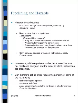
Hazards • 3 kinds • Structural hazards • Multiple instructions want to use same unit • Data hazards • Results of instruction needed before ready • Control hazards • Don’t know which side of branch to take • Will get back to this • First, how to pipeline when no hazards
IF • Stage 1: Instruction Fetch • Fetch a new instruction every cycle • Current PC is index to instruction memory • Increment the PC at end of cycle (assume no branches for now) • Write values of interest to pipeline register (IF/ID) • Instruction bits (for later decoding) • PC+4 (for later computing branch targets) • Anything needed by later pipeline stages • Next stage will read this pipeline register
IF instructionmemory addr mc 00 = read word +4 PC newpc
IF instructionmemory addr mc inst 00 = read word +4 Rest of pipeline PC+4 PC pcreg newpc pcrel pcabs pcsel IF/ID
ID • Stage 2: Instruction Decode • On every cycle: • Read IF/ID pipeline register to get instruction bits • Decode instruction, generate control signals • Read from register file • Write values of interest to pipeline register (ID/EX) • Control information, Rd index, immediates, offsets, … • Contents of Ra, Rb • PC+4 (for computing branch targets later)
result ID dest registerfile WE A A Rd D B B Rb Ra decode inst Stage 1: Instruction Fetch Rest of pipeline imm extend PC+4 PC+4 ctrl IF/ID ID/EX
EX • Stage 3: Execute • On every cycle: • Read ID/EX pipeline register to get values and control bits • Perform ALU operation • Compute targets (PC+4+offset, etc.) in case this is a branch • Decide if jump/branch should be taken • Write values of interest to pipeline register (EX/MEM) • Control information, Rd index, … • Result of ALU operation • Value in case this is a memory store instruction
pcsel branch? EX pcreg A D alu B imm B Stage 2: Instruction Decode Rest of pipeline pcrel + PC+4 target pcabs ctrl ctrl ID/EX EX/MEM
MEM • Stage 4: Memory • On every cycle: • Read EX/MEM pipeline register to get values and control bits • Perform memory load/store if needed • address is ALU result • Write values of interest to pipeline register (MEM/WB) • Control information, Rd index, … • Result of memory operation • Pass result of ALU operation
pcsel branch? MEM pcreg D D addr B M din dout Stage 3: Execute Rest of pipeline memory pcrel target mc pcabs ctrl ctrl EX/MEM MEM/WB
WB • Stage 5: Write-back • On every cycle: • Read MEM/WB pipeline register for values and control bits • Select value and write to register file
WB result D M Stage 4: Memory dest ctrl MEM/WB
instmem A A Rd D D D B B inst addr Rb Ra B M dout din imm +4 mem PC+4 PC+4 PC Rd Rd Rd Rt OP OP OP ID/EX EX/MEM MEM/WB IF/ID
Example: : Sample Code (Simple) • add r3, r1, r2; nand r6, r4, r5; lw r4, 20(r2); add r5, r2, r5; sw r7, 12(r3);
Example: Sample Code (Simple) • Assume eight-register machine • Run the following code on a pipelined datapath add r3 r1 r2 ; reg3 = reg 1 + reg 2 nandr6 r4 r5 ; reg6 = ~(reg 4 & reg 5) lwr420 (r2) ; reg4 = Mem[reg2+20] add r5 r2 r5 ; reg5 = reg 2 + reg 5 swr7 12(r3) ; Mem[reg3+12] = reg 7 Slides thanks to Sally McKee
+ A L U M U X 4 target PC+4 PC+4 0 R0 R1 regA ALU result R2 Register file regB valA M U X PC Inst mem Data mem instruction R3 ALU result mdata R4 valB R5 R6 M U X data R7 imm dest extend valB Bits 11-15 Rd dest dest Bits 16-20 M U X Rt Bits 26-31 op op op ID/EX EX/MEM MEM/WB IF/ID
At time 1, Fetch add r3 r1 r2 + A L U M U X 4 0 0 0 0 R0 0 36 R1 0 9 R2 Register file 0 M U X PC Inst mem Data mem nop 12 R3 0 0 18 R4 7 0 R5 41 R6 M U X data 22 R7 0 dest extend 0 Initial State Bits 11-15 0 0 0 Bits 16-20 M U X 0 Bits 26-31 nop nop nop ID/EX EX/MEM MEM/WB IF/ID
+ A L U add 3 1 2 M U X 4 0 4 0 / 4 0 R0 0 36 R1 0 9 R2 Register file 0 M U X PC Inst mem Data mem / 36 add 3 1 2 12 R3 0 0 18 R4 7 0 / 9 R5 41 R6 M U X data 22 R7 0 dest extend 0 Fetch: add 3 1 2 Bits 11-15 / 3 0 0 0 Bits 16-20 / 2 M U X 0 Bits 26-31 nop / add nop nop ID/EX EX/MEM MEM/WB IF/ID / 2 Time: 1
+ A L U nand 6 4 5 add 3 1 2 M U X 4 0 / 4 8 4 / 8 0 R0 0 36 R1 1 0 36 9 R2 Register file 2 36 M U X PC Inst mem Data mem / 18 nand 6 4 5 12 R3 0 0 / 45 18 R4 9 7 9 / 7 R5 41 R6 M U X data 22 R7 3 dest extend 0 / 9 Fetch: nand 6 4 5 Bits 11-15 / 6 3 3 0 0 / 3 Bits 16-20 / 5 M U X 2 Bits 26-31 add / nand nop nop / add ID/EX EX/MEM MEM/WB IF/ID / 3 Time: 2
+ A L U lw 4 20(2) nand 6 4 5 add 3 1 2 nand () 18 = 01 0010 7 = 00 0111 ------------------ -3 = 11 1101 M U X 4 4 / 8 12 8 0 R0 0 36 R1 4 0 / 45 / 18 36 9 R2 Register file 5 18 M U X PC Inst mem Data mem lw 4 20(2) 12 R3 45 0 / -3 18 R4 / 7 9 7 7 R5 41 R6 M U X data 22 R7 6 dest extend 9 / 7 Fetch: lw 4 20(2) Bits 11-15 3 3 6 3 0 / 6 / 3 Bits 16-20 2 M U X 5 Bits 26-31 nand add / nand nop / add ID/EX EX/MEM MEM/WB IF/ID / 4 Time: 3
+ A L U add 5 2 5 lw 4 20(2) nand 6 4 5 add 3 1 2 M U X 4 8 16 12 0 R0 0 36 R1 2 45 18 9 R2 Register file 4 9 M U X PC Inst mem Data mem add 5 2 5 12 R3 -3 0 18 R4 45 7 7 18 R5 41 R6 M U X data 22 R7 20 dest extend 7 Fetch: add 5 2 5 Bits 11-15 6 3 6 0 6 3 Bits 16-20 5 M U X 4 Bits 26-31 lw nand add ID/EX EX/MEM MEM/WB IF/ID Time: 4
+ A L U sw 7 12(3) add 5 2 5 lw 4 20 (2) nand 6 4 5 add 3 1 2 M U X 4 12 20 16 0 R0 0 45 36 R1 2 -3 9 9 R2 Register file 5 9 M U X PC Inst mem Data mem sw 7 12(3) 45 R3 29 0 18 R4 -3 7 7 R5 41 R6 M U X data 22 R7 20 5 dest extend 18 Fetch: sw 7 12(3) Bits 11-15 0 6 3 4 5 4 6 Bits 16-20 4 M U X 5 Bits 26-31 add lw nand ID/EX EX/MEM MEM/WB IF/ID Time: 5
+ A L U sw7 12(3) add 5 2 5 lw 4 20(2) nand 6 4 5 M U X 4 16 20 0 R0 0 -3 36 R1 3 29 9 9 R2 Register file 7 45 M U X PC Inst mem Data mem 45 R3 16 99 18 R4 29 7 7 22 R5 -3 R6 M U X data 22 R7 12 dest extend 7 No more instructions Bits 11-15 5 4 6 5 0 5 4 Bits 16-20 5 M U X 7 Bits 26-31 sw add lw ID/EX EX/MEM MEM/WB IF/ID Time: 6
+ A L U nopnopsw 7 12(3) add 5 2 5 lw 4 20(2) M U X 4 20 0 R0 0 36 R1 16 45 9 R2 Register file M U X PC Inst mem Data mem 45 R3 99 57 0 99 R4 16 7 R5 -3 R6 M U X data 22 R7 12 dest extend 22 No more instructions Bits 11-15 0 5 4 7 7 5 Bits 16-20 7 M U X Bits 26-31 sw add ID/EX EX/MEM MEM/WB IF/ID Time: 7
+ A L U nopnopnopsw7 12(3) add 5 2 5 M U X 4 0 R0 16 36 R1 57 9 R2 Register file M U X PC Inst mem Data mem 45 R3 0 99 22 R4 57 16 R5 -3 R6 M U X data 22 R7 dest 22 extend No more instructions Bits 11-15 5 7 Bits 16-20 M U X Bits 26-31 sw ID/EX EX/MEM MEM/WB IF/ID Time: 8 Slides thanks to Sally McKee
+ A L U nopnopnopnopsw 7 12(3) M U X 4 0 R0 36 R1 9 R2 Register file M U X PC Inst mem Data mem 45 R3 99 R4 16 R5 -3 R6 M U X data 22 R7 dest extend No more instructions Bits 11-15 Bits 16-20 M U X Bits 21-23 ID/EX EX/MEM MEM/WB IF/ID Time: 9
Takeaway • Pipelining is a powerful technique to mask latencies and increase throughput • Logically, instructions execute one at a time • Physically, instructions execute in parallel • Instruction level parallelism • Abstraction promotes decoupling • Interface (ISA) vs. implementation (Pipeline)
Hazards See P&H Chapter: 4.7-4.8
Hazards • 3 kinds • Structural hazards • Multiple instructions want to use same unit • Data hazards • Results of instruction needed before • Control hazards • Don’t know which side of branch to take
Data Hazards • What about data dependencies (also known as a data hazard in a pipelined processor)? • i.e. add r3, r1, r2 • sub r5, r3, r4 • Need to detect and then fix such hazards
Why do data hazards occur? • Data Hazards • register file reads occur in stage 2 (ID) • register file writes occur in stage 5 (WB) • instruction may read (need) values that are being computed further down the pipeline • In fact this is quite common • destination reg of earlier instruction == source reg of current stage left “earlier” = started earlier = stage right
IF IF IF IF IF Data Hazards Clock cycle 1 2 3 4 5 6 7 8 9 time MEM WB ID add r3, r1, r2 subr5, r3, r4 MEM WB ID lw r6, 4(r3) MEM WB ID orr5, r3, r5 MEM WB ID swr6, 12(r3) MEM WB ID
iClicker How many data hazards due to r3 only 1 2 3 4 5 add r3, r1, r2 subr5, r3, r4 lw r6, 4(r3) orr5, r3, r5 swr6, 12(r3)
IF IF IF IF IF Data Hazards Clock cycle 1 2 3 4 5 6 7 8 9 time r3 = 10 r3 = 20 r3 = 10 MEM WB ID 1. add r3, r1, r2 r3 = 10 r3 = 20 2. subr5, r3, r4 MEM WB ID r3 = 10 3. lw r6, 4(r3) MEM WB ID r3 = 10 4. orr5, r3, r5 MEM WB ID OK 5. swr6, 12(r3) MEM WB ID
Data Hazards • What about data dependencies (also known as a data hazard in a pipelined processor)? • i.e. add r3, r1, r2 • sub r5, r3, r4 • How to detect?
Detecting Data Hazards add r3, r1, r2 sub r5, r3, r5 or r6, r3, r4 add r6, r3, r8 instmem A A Rd D D D B B inst addr Rb Ra B M dout din imm +4 mem detecthazard PC+4 PC+4 PC Rd Rd Rd Rt for rA (IF/ID.rA ≠ 0 && (IF/ID.rA==ID/Ex.Rd IF/ID.rA==Ex/M.Rd IF/ID.rA==M/W.Rd)) OP OP OP ID/EX EX/MEM MEM/WB IF/ID
Detecting Data Hazards • Data Hazards • register file reads occur in stage 2 (ID) • register file writes occur in stage 5 (WB) • next instructions may read values about to be written • In fact this is quite common • How to detect? (IF/ID.Ra != 0 && • (IF/ID.Ra == ID/EX.Rd || IF/ID.Ra == EX/M.Rd || IF/ID.Ra == M/WB.Rd)) • || (same for Rb) • destination reg of earlier instruction == source reg of current stage left “earlier” = started earlier = stage right
Next Goal • What to do if data hazard detected? • Options • Nothing • Change the ISA to match implementation • Stall • Pause current and subsequent instructions till safe • Forward/bypass • Forward data value to where it is needed