Injection Molding
Injection Molding. Introduction Injection Molding Machines and Operations Safety Polystyrenes Dimension Stability Measure Residu al Stress Using Photoelasticity Weld-line Influence on Strength Breaking Gear Teeth. Importance of Plastics.

Injection Molding
E N D
Presentation Transcript
Injection Molding • Introduction • Injection Molding Machines and Operations • Safety • Polystyrenes • Dimension Stability • Measure Residual Stress Using Photoelasticity • Weld-line Influence on Strength • Breaking Gear Teeth ME495 Laboratory II-IM-
Importance of Plastics Plastic industry ~ 100 billion/yr business, 1.4 million production jobs World consumption of raw material by weight ME495 Laboratory II-IM-
Importance of Injection Molding for Plastics Plastic consumption by processes ME495 Laboratory II-IM-
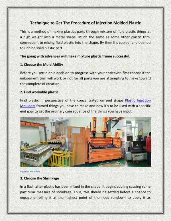
Injection Molding Machines (1000GGB) ME495 Laboratory II-IM-
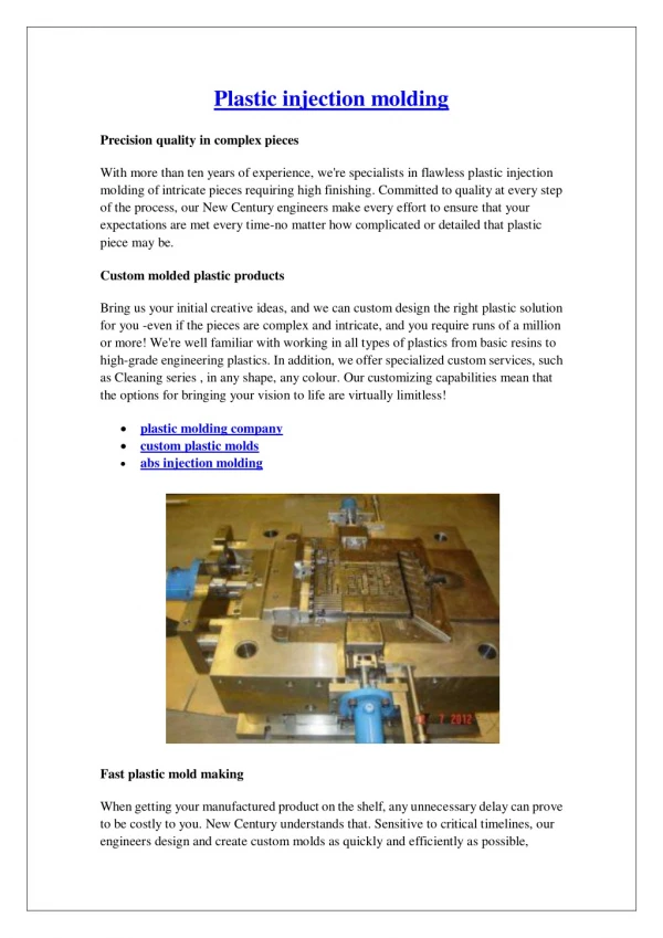
Basic Elements of an Injection Molding Machine Material hopper Gear train Mold Motor Screw Hydraulic pressure Clamping Unit Heaters Limit switches Spline Main IM machine spec. include clamp force (tons), shot size (ounces or pounds) and injection rate (in3/sec) ME495 Laboratory II-IM-
The Basic Operation 1. Raising the temperature of the plastic to melt it. This is achieved by heaters and the screw (mixing + friction heat). This overall process is called plastification of the material. 2. Inject the melted plastic (through various flow channels) into the mold cavity and allow it to solidify in the mold. 3. Open the mold and eject the product ME495 Laboratory II-IM-
Typical IM Process Cycle ME495 Laboratory II-IM-
Functions of IM Elements ME495 Laboratory II-IM-
Safety • The barrel temperature is usually 350-550° F (177-288°C), and can be as high as 700° Fahrenheit (371° Celsius). • Plastic at its molding temperatures is hot and sticky. If it gets on skin or clothes, usually it is not easy to remove it. ME495 Laboratory II-IM-
Safety (cont.) • The electrical wires to the heater bands are high voltage (typically 460 volts) and very high current. • Operating personnel must be aware of all the moving parts in the molding machine. Protective guards are placed around potentially hazardous areas but caution from operators is still necessary. ME495 Laboratory II-IM-
Polystyrenes Polystyrenes (Comes in two forms: foam and solid) - Foamed polystyrene is used to make cups, bowls, plates, trays, clamshell containers, meat trays and egg cartons as well as protective packaging for shipping electronics and other fragile items. - Solid polystyrene is used in products such as cutlery, yogurt and cottage cheese containers, cups, clear salad bar containers and video and audiocassette housings. Recycling Symbols ME495 Laboratory II-IM-
Mechanical Properties of Various Plastics ME495 Laboratory II-IM-
Thermoplastic Glass transition temperature Low thermal conductivity (good insulator) Extremely high viscosity (high pumping pressure and losses) Viscosity is temperature sensitive Non–Newtonian: Viscosity decreases as shear rate increases (shear thinning) Thermofluid Properties of Polymers ME495 Laboratory II-IM-
Temperature and Shear–rate Dependence of Viscosity ME495 Laboratory II-IM-
IM process is quite complicated Molding parameters and part properties are linked through fluid flow. We will limit ourselves to 2 variables: temperature and flow rate ME495 Laboratory II-IM-
Lab 1 Process Parameters 190oC, 200oC, and 210oC at 600 bar 5–6 parts/condition ME495 Laboratory II-IM-
Problems from Improper Processing • “Short shots” — results when insufficient polymer is injected into the mold. • “Flash” — caused by excessive packing and/or holding pressure prying open the mold and driving polymer through the resulting crack • Dimensional instability — from removing part without proper cooling time • “Sink marks” — caused by excessive shrinkage of the polymer during the cooling cycle ME495 Laboratory II-IM-
Importance of Proper Temperature and Pressure Pressure: without proper holding pressure, excessive shrink mark or flashing may result Temperature: Too high: chemical degradation, cooling time, shrink mark Too low: high viscosity ME495 Laboratory II-IM-
Dimensional Stability (Shrinkage) At temperatures higher than T2 = Tg(shown below), the higher energy level of molecules creates a “free volume”. This free volume may be “frozen in” during rapid cooling. Theoretical density at 0, 10, 100 and 210 sec during quenching (PS) ME495 Laboratory II-IM-
Effect of manufacturing parameters on quality • Gear strength is influenced by • Shrinkage (gear size and geometry) • Homogeneity (weld line? Residual stress due to uneven cooling?) ME495 Laboratory II-IM-
Effect of Flow Orientation on Strength ME495 Laboratory II-IM-
Effect of Weld Line on Strength ME495 Laboratory II-IM-
Measure Residue Stress by Photoelasticity Photoelasticity is a nondestructive, graphic stress-analysis technique based on the birefringence property possessed by many transparent polymers. It is mainly used for 2-dimensional (planar) problems. A polariscope (polarimeter) measures birefringence in specimens. It consists of a light source, a polarizer, an optional quarter-wave plate, a specimen, another optional quarter-wave plate, and a second polarizer called the analyzer. ME495 Laboratory II-IM-
Working Principle of Polariscopes The theory of photoelasticity is based on light refraction that depends on the orientation of polarized light Refraction: When light passes through any medium other than a vacuum, its velocity decreases ME495 Laboratory II-IM-
Double Refraction If similar light waves pass through the same thickness h of two media having indices of refraction n1 and n2, a phase difference d between the two waves after they emerge from the media results ME495 Laboratory II-IM-
Birefringence Photoelastic materials are birefringent, i.e., they refract light differently depending upon the state of stress in the material. In an unloaded state, the material exhibits an index of refraction n0 independent of orientation. In the loaded state, however, the magnitudes of the principal stresses, determine the index of refraction for that light wave. The change in index of refraction is found to be (Maxwell Equations) For birefringentmaterial, c1 c2. Stress-optic coefficients ME495 Laboratory II-IM-
Example Birefringence Patterns crack tensile bending ME495 Laboratory II-IM-
Additional Safety Issues • Sessions 1&2 involve bending fracture of the gears, so it is very important to wear safety glasses in the lab. ME495 Laboratory II-IM-
Torque Test Single tooth: Torque is carried by one tooth‚ easier to analyze. Normal engagement: true torque capacity of the gear. ME495 Laboratory II-IM-
Model the gear tooth as a rectangular prism: Thickness b Force W Length L width h ME495 Laboratory II-IM-
Predicting Gear Strength • Given the gear geometry you can relate gear torque to the stress at the root of a gear tooth. • If you knew the stress that would cause the polystyrene to fail in tension‚ you could predict the torque at which the gear teeth would fail. • Guess what you’ll be doing in lab next week? ME495 Laboratory II-IM-
Process Conditions for Session #2 Polystyrene: 190oC, 200oC, 210oC 500 bar 5 parts each for the case with and without weld lines ME495 Laboratory II-IM-
Analysis of Session 1 Results • Make gears at given temperatures and flow rates. Qualitatively explain which combinations of processing conditions lead to short shot, flash and sink marks. How do processing conditions affect final part dimensions? • Measure pertinent geometrical quantities, including contact point position when two gears are meshed together. • From your optical observations, identify regions of high residual stress in molded part. Qualitatively assess effect of injection rate and melt temperature (processing parameters) on residual stress field. What other processing parameters will impact residual stress field? Qualitatively explain why residual stress is concentrated only in certain regions. ME495 Laboratory II-IM-
Analysis of Session 1 Results, Continued • Break gear teeth and record failure torque. Does failure torque depend on temperature or flow rate? • Perform a strength analysis on gear and relate failure torque to gear tooth stress. You will measure failure stress for polystyrene in Session 2. • Observe fill and cooling times of current injection molding cycle. Also observe and record mold temperature for your analysis and computer simulation. ME495 Laboratory II-IM-