Download
1 / 39
520 likes | 1.87k Vues
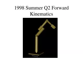
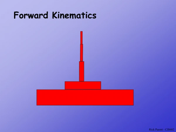
The Forward Kinematics of Manipulators. Sebastian van Delden USC Upstate svandelden@uscupstate.edu. Kinematics. Kinematics is the science of motion that treats the subject without regard to the forces that cause it. Forward Kinematics of Manipulators:

E N D
The Forward Kinematics of Manipulators Sebastian van Delden USC Upstate svandelden@uscupstate.edu
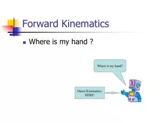
Kinematics • Kinematics is the science of motion that treats the subject without regard to the forces that cause it. • Forward Kinematics of Manipulators: • compute position and orientation of the end effector given a set of joint angles. • EASY(er) • Inverse Kinematics of Manipulators: • given the position and orientation of the end effector, calculate all possible joint angles that could achieve this position and orientation. • HARD • Stäubli RX60s – As many as 8 possible ways to achieve end effector pose
Link Descriptions • N dof manipulators have N joints and N-1 rigid links that connect them. • Link 0 is the non-moving link at the base • Link 1 is the first moving link, etc… • Our Stäubli RX60s have 6 revolute joints.
Link Descriptions cont… • Link Length, a, is the distance between joints. • Link Twist, , is the angle difference between axes of two joints. • Picture a vector pointing from jointi-1 to jointi and then rotate jointi until it is inline with jointi-1. • Joints axes are vectors that run though the center of the joint. • End points are given a value of 0.
Link-Connection Description • Describes the joint. • Link Offset, d, and the distance between ai-1 and ai. • Joint Angle, θ, is the angle between ai-1 and ai. • End points are given a value of 0.
Link parameters • For revolute joints, θ varies. • For prismatic joints, d varies. • The pose of a manipulator can be defined in terms of these link and link-connection parameters. • A Denavit-Hartenburg Table (DH Table) can be used to represent all of these parameters.
Attaching Frames to Links • Z axes are coincident with the joint axes. • X axes point along a to the next joint, or if Zs intersect then X is normal to this plane. • Y can then be automatically determined. • Each joint has a frame attached to it, frames {0}, {1}, {2}, {3}, etc.. • {0} is attached to the non-moving base and is usually aligned initially with {1}. • To calculate forward kinematics, we just need to find the transformations that describe the chain frames.
Example • Attach frames to the following manipulators and populate the DH Table.
Example cont… • The DH Table
Another Example • Frames can be assigned in different ways! • Consider this RRR machine
Another Example cont… • Two possible frame assignments!
Another Example cont… • Two more assignments!
Derivation of Link Transformation • We need to derive the transformation from frame {i} to frame {i-1}. • This transformation can be broken down into sub-problems and intermediate frames {P}, {Q}, and {R}. • To get from frame {i-1} to {R}, rotate by degrees around X. • To get from {R} to {Q}, translate by a mm. • To get from {Q} to {P}, rotate by the θ degrees around Z. • To get from {P} to frame {i}, translate by d mm.
Deriving the Link Transformation • So the transformation from {i-1} to {i} is: • Which can also be written as:
Deriving the Link Transformation • Multiplying out, we get: • Multiply all link transformation together to compute forward kinematics.
Example: PUMA 560 • Multiplying out the transformations: