Solar Installation Best Practices Bootcamp
Solar Installation Best Practices Bootcamp. Noel Cotter August Goers Solar Power 2008. About Us – Noel Cotter. About Us – August Goers. Getting to Know Each Other. General show of hands. Who is: Looking to get starting in the solar installation business but not started yet

Solar Installation Best Practices Bootcamp
E N D
Presentation Transcript
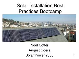
Solar Installation Best Practices Bootcamp Noel Cotter August Goers Solar Power 2008
Getting to Know Each Other General show of hands. Who is: • Looking to get starting in the solar installation business but not started yet • Have installed a few systems or helped install a few systems • Consider yourself and experienced installer but want to broaden you experience • Not an installer, but in a support role such as sales, management, manufacturing, etc. • NABCEP Certified PV Installer • Located in CA • Located in USA outside of CA • Located outside of USA
Today • We will walkthrough hands-on installation considerations from initial site assessment through post installation inspections for standard residential and small commercial PV systems • We will focus on what to do and importantly, what NOT TO DO • Discuss controversial issues and work towards resolutions
Overview of today’s schedule • 9:00 – 10:30: intro, safety overview, site assessment review, design review, orientation and shading study • 10 minute break • 10:40 – 12:00: system installation process focusing on roof area including material selection • 1 hour lunch break • 1:00 – 2:15: transition wiring, conduit, junction boxes, grounding • 10 minute break • 2:25 – 4:00: inverter installation considerations, electrical considerations, labeling, final checklist, Q&A
Best Practices – An Interactive Course • We want to hear your ideas • There is always more than one way to get it done and differing opinions – we’ll try to present both sides of the story when possible • Define a best practice as “a technique or methodology that through experience and research has proven to reliably lead to a desired result.”
What is the “desired result?” • System installed for a balance of maximum efficiency versus aesthetics • Built to last and perform for 25+ years • Installed in an economical manner – we don’t want to unnecessarily drive up costs • Continued improvement - installation quality and efficiency should be ever improving
NABCEP Continuing Education Credits • This class is approved for NABCEP continuing education credits (CEC #1008-6) • 6 hours related to the NABCEP task analysis field • http://www.nabcep.org/cedrecert.cfm • Send a copy of your certificate of completion to NABCEP to register the credits
NABCEP PV Installer Task Analysis • Working Safely with Photovoltaic Systems • Conducting a Site Assessment • Selecting a System Design • Adapting the Mechanical Design • Adapting the Electrical Design • Installing Subsystems and Components at the Site • Performing a System Checkout and Inspection • Maintaining and Troubleshooting a System
Safety first • Utmost importance, but not the focus of this class • OSHA (Occupational Safety and Health Administration) regulations Volume 29 of the U.S. Code of Federal Regulations (CFR) • Constantly keep safety in mind and discuss it on a daily basis • Provide safety training, employers of 11 or more must maintain a record of occupational injuries and illnesses • Regular weekly safety meetings with logs
Safety first 29 CFR Part 1926 subparts • C: General Safety and Health Provisions • D: Occupational Health and Environmental Controls • E: Personal Protective and Life Saving Equipment • I: Tools, Hand and Power • K: Electrical • M: Fall Protection • X: Stairways and Ladders
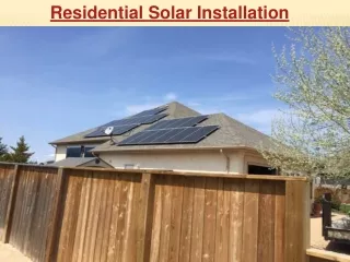
Site assessment review • We’ll assume a qualified technician came out and assessed the site • Use a customer intake worksheet • Find target system size • Find electrical loads from previous bills or complete load worksheet • See if the mounting location (usually the roof) can hold desired quantity of panels • Find optimal array location based on • Orientation • Shading • Physical limitations • Aesthetics
Site assessment review • Assure structure can support desired array • Take plenty of site photos, use Google Earth • Assure the electrical provisions can handle proposed system (especially NEC 690.64) • Estimate difficulty of job • Customer budget, targets, etc
System design review • We’ll assume a qualified individual designed the system • For those of you just getting started - most manufactures or dealers offer comprehensive design courses • Consult with your local jurisdiction to obtain details on permit and or local design requirements
System design review • Installer should be supplied with: • Basic site diagram w/ major component identification • Electrical diagram w/ array information listing electrical component requirements • Component specification sheets (“cut sheets”) • Inverter • Modules • Racking • Other manufacturer installation manual(s)
Shading: PV’s worst enemy • Why is shade such a concern? • Always use a shade detection tool such as the Solmetric Suneye or the SolarPathfinder • Maximum Power Point (MPP) tracking and effects from shading • Inverters have a MPP voltage range window – must keep within
String shading study • Two stings of 10 Sunpower 230 W modules • Module characteristics (at STC): • Vmp = 41.0 V • Voc = 48.7 V • Imp = 5.61 A • Isc = 5.99 A • String characteristics (at STC): • Vmp = 410 V • Voc = 487 V • Imp = 11.22 A • Isc = 11.8 A
String shading study • Use manufacturer sizing calculator to configure strings • This example uses a Sunpower 5000m inverter with a MPP tracking range of 250 – 480 V
String shading study • First case – start shading panels on one string only, one by one
String shading study • Second case – start shading panels in both strings
Strings and Orientation • Rules: • Never mix different panel models onto a single inverter • Never orient panels in the same string in different directions • Try to maximize number of panels in a string • For tilt rows, lower pitch is generally better concession compared to causing interrow shading • Always angle panels to at least 5° to allow rain wash
Tilt and Orientation notes • Southern direction tilted to latitude is generally best for maximum year round harvest • Latitude +/- 15° for South facing arrays also works well • West direction works well with utility time-of-use rates • Lower tilts for East and West arrays are preferable
Overview of installation sequence • If possible lead installer should arrive to site before crew to walkthrough plan • Review plans, review general location of array(s), conduit run(s), and inverter(s) • Walk through final installation plan with building owner or stakeholders to clarify expectations • Up on the roof • Roughly position array(s) • Determine conduit run • Determine location for junction box(es)
Overview of installation sequence • Determine inverter mounting location • Locate AC and or DC disconnect(s) locations as applicable • Finalize conduit path • Walkthrough installation sequence plan with crew prior to starting work
Recommended crew configuration • Crew size of three is typically ideal for standard residential and small commercial projects • Crew lead and beginning installer start on roof working on layout and racking • Experienced installer works down below installing inverter and conduit • Crew members can work together when necessary
Array layout • Balance between • Design towards maximum performance • Available roof or mounting space • Shading considerations • Orientation • Aesthetics
Aesthetics considerations • Try to get away from the 70s and 80s mentality of “efficiency at all costs” – gives solar a bad name • Make sure the client is happy with how it will look • Generally, keep panels flush with roof on pitched roofs • On flat roofs tilt panels up to latitude depending on aesthetics and time of use considerations • Try to keep racking low profile on pitched installations, if visible from below
Array layout techniques • Find the joists/rafters, mark each with chalk line • Methods of finding rafters: • Mark exposed rafters from eave up • Go into attic or view exposed rafters, transfer measurements to roof • Tap the roof with a hammer • Use a heavy duty stud finder
Array layout techniques • Center the array(s) over the rafters • Clearly draw array boundaries with crayon, marker, or soapstone • Determine which rafters to fasten to, spacing is dependent on manufacturer instructions • If necessary, move array boundaries again to center array over chosen rafters • Using chalk line, mark all penetration points
Roof penetrations • Always look into the attic or ceiling before making roof penetrations when possible • Must always hit structural members unless using specially designed racking system • Use 1/8” or 3/16” diameter long bits to make pilot hole – don’t go any deeper than the depth of the lag bolt
Roof penetrations • Gently lower and raise drill while drilling to view wood chips • On comp shingle, gently lift and peel back shingle before making penetration • Mark then seal any missed holes immediately with aluminum flashing and sealant – before you forget! • Drill manufacturer recommended pilot hole size
Overview of panel racking sequence • Mount all stanchions • Mount racking to stanchions according to manufacturer instructions – use string line, keep it square and plumb • Assure racking is square to roof ridge or edge • Use a long straightedge to assure all rails (if used) are level and in same plane
Overview of panel racking sequence • Mount transition wiring junction box • Mount racking grounding lugs and run ground wire • Run conduit under array • Run string line with C-clamps on 1st (normally lower) row of panels • Mount panels • Wire panels in strings and affix wiring • Adjust and trim racking
Interlude – Working on tall/steep roofs • Strap in w/ OSHA approved gear • Fasten roof hooks to peak • Install toe boards • Run ladder up roof if there is support from below • Install lower row of standoffs first to work off • Clip tools and materials to work belt • Fasten materials and tool bags to vent pipes • Use scaffolding for dangerous jobs
Material selection – roof mount points • Many options available • Examples include, but not limited to, Unirac standoffs, Professional Solar Products Fast Jacks, Conergy SunTop, Sharp SRS, Quickmount PV, Thompson Technologies Flat Jack, etc. • L-brackets are not recommended
Material selection - Sealants • First rule: A properly flashed roof penetration should require sealants only as a second line of defense – we’ll get into specifics later • IBC: Section 1503.2.1: "Flashing shall be installed . . . . (4) around roof openings" . . ."Where flashing is of metal the metal shall be corrosion resistant with a thickness of not less than 0.019 in (26 gauge galvanized sheet)"
Materials selection - Sealants • Make sure sealants are compatible with roofing materials and designed to last • Asphalt based – a large variety available, cracks and wears out over time, quality varies • Polyeurethane sealant such as Sikaflex 1A or Sikaflex Construction Sealant – no good for asphalt or bituminous materials • Silicone – requires surface preparation and may not adhere properly, especially in damp work environments • Tripolymer - Geocell 2300 • Polyether – Chemlink M1