Download
1 / 35
430 likes | 1.01k Vues
Advanced Phasor Measurement Units for the Real- Time Monitoring of Transmission and Distribution Networks Paolo Romano Distributed Electrical Systems Laboratory École Polytechnique Fédérale de Lausanne - EPFL. Introduction PMU requirements Proposed synchrophasor estimation algorithm

E N D
Advanced Phasor Measurement Units for the Real-Time Monitoring of Transmission and Distribution Networks Paolo Romano Distributed Electrical Systems Laboratory ÉcolePolytechniqueFédérale de Lausanne - EPFL
Introduction PMU requirements Proposed synchrophasor estimation algorithm Algorithm implementation Experimental validation Conclusion Outline
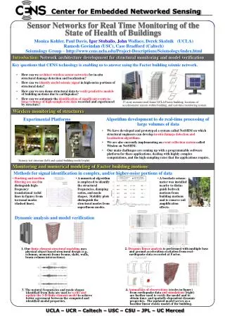
Evolution of distribution networks passive active major changes in their operational procedures; need of advanced and smarter tools to manage the increasing complexity of the grid; main involved aspect is the network monitoring by means ofPhasor Measurement Units (PMUs); Introduction (1)Power networks new paradigms PMU definition (as stated in IEEE Std.C37.118-2011): “A device that produces synchronized measurements of phasor(i.e. its amplitude and phase), frequency,ROCOF(Rate of Change Of Frequency) from voltage and/or current signals based on a common time source that typically is the one provided by the Global Positioning System UTC-GPS.”
PMU timeline: Introduction (2)What is a Phasor Measurement Unit (PMU)? PMU typical configuration: 1893 1980s 2005 1988 2012 2011 1992 1995 Introduction of “Phasor” concept New PMU Standard (IEEE C37.118 -2005) 1st PMU prototype 1st PMU Standard (IEEE 1344) 1st PMU prototype at EPFL Latest version of IEEE Std. C37.118-2011 1st commercial PMU GPS technology
Introduction (3)PMU applications within transmission networks
Introduction (4)PMU applications within active distrib. networks Phasor DataConcentrator - PDC RT Power System State Estimator • Network in emergency conditions: • Islanding detection • Fault identification • Fault location • Network in normaloperation: • Voltage sensitivities computation • Power flows sensitivities computation • V/P real time optimal control • Real time congestion management = Phasor Measurement Unit
PMU requirements (1)IEEE Std. C37.118-2011 - Definitions Synchrophasor definition:
Reporting rates: Performance classes: P-class: faster response time but less accurate M-class: slower response time but greater precision Measurement evaluation: PMU requirements (2)IEEE Std. C37.118-2011 – Measurement compliance
PMU requirements (3)Active Distribution Networks applications • Peculiar characteristics of distribution networks: • reduced line lengths; • limited power flows values; • high harmonic distortion levels; • dynamic behaviors Improved accuracy of synchrophasors measurements
PMU requirements (4)Active Distribution Networks applications synchrophasor #2 synchrophasor #1
Proposed synchrophasor est. algorithm (1)State of the Art of DFT based algorithms Considered error sources:
Proposed synchrophasor est. algorithm (2)State of the Art of DFT based algorithms Correction approaches:
Proposed synchrophasor est. algorithm (3)Structure of the proposed algorithm Signal acquisition (voltage/current), within a GPS-PPS tagged window T (e.g. 80 ms, i.e. 4 cycles at 50 Hz) with a sampling frequency in the order of 50-100 kHz. DFT analysis of the input signal, opportunely weighted with a proper window function. First estimate of the synchrophasor by means of an interpolated-DFT approach. Iterative correction of the self-interaction between the positive and negative image of the DFT main tone.
Proposed synchrophasor est. algorithm (4)Flow chart 3-4 periods of the fundamental frequency tone
Proposed synchrophasor est. algorithm (4)Flow chart Hanning window:
Algorithm implementation (1)FPGA-optimized software implementation
Algorithm implementation (2)FPGA-optimized software implementation • GPS-synchronization process: • Time uncertainty of ± 100 ns • Compensation of the FPGA clock drift • Pipelined signal acquisition: • 6 parallel channels (3 voltages 3 currents) • Phase correction • Synchrophasor estimation algorithm: • Optimized DFT computation for power systems typical frequencies • 32-bits fixed-point implementation
Experimental validation (1)Compliance verification platforms • HW - PXI based platform: • SW - Desktop based platform: • Generate the test signal in host according to each test item in IEEE C37.118, 2011 then run the FPGA algorithm in desktop. Control and synchronization of the other PXI boards Time-Sync accuracy ±100 ns with 13 ns standard deviation 18-bit resolutioninputsat 500 kS/s, analog input accuracy 980 μV over ±10 V input range (accuracy of 0.01%)
Experimental validation (2)Static tests – Signal frequency range
Experimental validation (3)Static tests – Harmonic distortion
Experimental validation (4)Dynamic tests – Amplitude-phase modulation
Conclusions (1)Future improvements • Design of a iDFT algorithm satisfying both class P and M requirements: • Sensitivity to algorithm parameters (Fs, N, w(n), interpolation scheme, no. of iteration) • Out of band interference test compliance (signal pre-filtering) • Adaptation of the algorithm to specific hardware platform: • NI-9076 (SIL-nanotera) • Zynq • Integration of GPS-independent synchronization systems: • Autonomous clocks (e.g. Rubidium-Oscilloquartz) • External synchronization signals provided by telecom protocols (Alcatel)
The end THANK YOU VERY MUCH FOR YOU ATTENTION