Optimizing Air Cooling in PSB Dump: Effects of Fins Geometry on Performance
This study investigates the air cooling efficiency of a PSB Dump through CFD simulations, analyzing different fin geometries ranging from ‘5mm-10mm-10mm’ to ‘5mm-25mm-50mm’. The simulations account for heat transfer and turbulence in steady-state conditions, with a focus on the impacts of smooth and sharp duct connections on pressure drop and temperature distribution. Key findings reveal how fin configurations influence air velocity and heat exchange, providing insights for enhanced thermal performance in engineering applications.

Optimizing Air Cooling in PSB Dump: Effects of Fins Geometry on Performance
E N D
Presentation Transcript
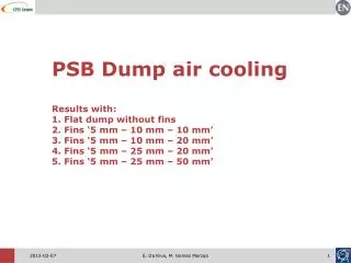
PSB Dump air coolingResults with:1. Flat dump without fins 2. Fins ‘5 mm – 10 mm – 10 mm’ 3. Fins ‘5 mm – 10 mm – 20 mm’4. Fins ‘5 mm – 25 mm – 20 mm’5. Fins ‘5 mm – 25 mm – 50 mm’ E. Da Riva, M. Gomez Marzoa
Contents1. Set-up and geometry2. Pressure drop with “smooth” and “sharp” connection3. Temperature results with different fins geometries4. Some detailed results E. Da Riva, M. Gomez Marzoa
CFD model setup & boundary conditions • Air flow and heat transfer in the fluid and solid solved all together in a single simulation. • Steady-state simulation. • Turbulence model : Standard k-ε +standard wall functions. • Gravity and buoyancy taken into account (even if not really relevant in this case). • Dependence of air conductivity, viscosity and constant heat on temperature taken into account. • Thermal conductivity of copper C18150: 320 W m-1 K-1 (temperature independent). • Inlet flow rate: 1800 m3 h-1 (→ 15 K air temperature rise, 12.5 m/s air velocity in the ducts). • Air injected from the ducts. • Air temperature at inlet: 20 °C. • Energy deposition inside the dump: imported from FLUKA file (~9500 W). E. Da Riva, M. Gomez Marzoa
CFD model: geometry PSB Dump Beam pipe Air duct Full geometry: symmetry applied in the model 8 L min-1, 0.5 W cm-2 PSB Dump Beam pipe Beam pipe separated 1 cm from dump. E. Da Riva, M. Gomez Marzoa
2 geometries considered in the CFD simulations: Duct connection geometry “smooth connection” B. “sharp connection” • 159 mm i.d. for both duct & connection Actual geometry from CATIA model: PSB Dump • ~160 mm i.d. for the duct • ~150 mm i.d. for the connection • Inner surface of the duct end rounded • 150 mm internal diameter • 150 mm bending radius E. Da Riva, M. Gomez Marzoa
Pressure drop results “Smooth connection” B. “Sharp connection” Gauge pressure at 1800 m3h-1[Pa]. E. Da Riva, M. Gomez Marzoa
Energy deposition Energy deposition in the dump [W m-3]. • Heat generation inside the dump imported from FLUKA file: ~9450 W total power. E. Da Riva, M. Gomez Marzoa
The solution of “thin fins” brazed on the dump is neglected because of manufacturing consideration. • Only “bulky fins” machined on the dump cylinder are taken into considerations • Diameter of dump: 400 mm at the foot of the fins. • 3 different dump surfaces simulated: Fins geometry r = 220 mm r = 200 mm ‘5-10-10’ fins. ‘5-10-20’ fins. ‘5-25-20’ fins. ‘5-25-50’ fins. E. Da Riva, M. Gomez Marzoa
Temperature at the symmetry plane [°C]. CFD results: temperature B. ‘5-10-10’ fins A. ‘no fins’ C. ‘5-10-20’ fins D. ‘5-25-20’ fins E. ‘5-25-50’ fins E. Da Riva, M. Gomez Marzoa
Detailed results for ‘5-10-20’ fins(aka ‘didactic fancy pictures’) E. Da Riva, M. Gomez Marzoa
Velocity (5-10-20 fins, 1800 m3h-1) Velocity at the symmetry plane [m s-1]. E. Da Riva, M. Gomez Marzoa
Temperature (5-10-20 fins, 1800 m3h-1) Temperature [°C] at 0.5 m from the front (hot) end of the dump. • Note that the air flowing between the fins is locally much warmer than the average out air temperature (35°C) → important to take into account the dependency of air properties on temperature. • Homogeneous temperature of fins → no problem of thermal fins efficiency (on copper side). E. Da Riva, M. Gomez Marzoa
Temperature (5-25-20 fins, 1800 m3h-1) Temperature [°C] at 0.5 m from the front (hot) end of the dump. E. Da Riva, M. Gomez Marzoa
Temperature (5-25-50 fins, 1800 m3h-1) Temperature [°C] at 0.5 m from the front (hot) end of the dump. E. Da Riva, M. Gomez Marzoa
Velocity (5-10-20 fins, 1800 m3h-1) • The area available for the air flow between the dump (D=400 mm at the foot of fins) and the shielding (D=500 mm) is extremely important since it determines the air velocity and therefore the heat transfer coefficient. • Note that the air velocity in the gap between 2 fins is smaller than far away from the fins → the local heat transfer coefficient is reduced. E. Da Riva, M. Gomez Marzoa
Velocity (5-25-20 fins, 1800 m3h-1) • Increasing the gap between the fins, a more favorable velocity is locally achieved, however the total surface available for the heat transfer is reduced. • The geometry ‘5-25-20’ performs better than ‘5-10-10’ (168°Cvs188°C, same total area available). • The geometry ‘5-10-20’ performs better than ‘5-25-20’ (150°Cvs168°C) because the highertotal area availableis the dominating effect. E. Da Riva, M. Gomez Marzoa
Velocity (5-25-50 fins, 1800 m3h-1) • The area available for the air flow between the dump (D=400 mm at the foot of fins) and the shielding (D=500 mm) consists in closed ducts and the air flow is better exploited. • The ducts on the top display a higher velocity. E. Da Riva, M. Gomez Marzoa
Heat flux (5-10-20 fins, 1800 m3h-1) Local heat flux [W m-2]. • The highest heat flux is achieved at the top of the fins. • The surface at the foot of fins is not ideally exploited because of the local reduced air velocity. E. Da Riva, M. Gomez Marzoa
Heat flux (5-25-20 fins, 1800 m3h-1) Local heat flux [W m-2]. E. Da Riva, M. Gomez Marzoa
Heat flux (5-25-50 fins, 1800 m3h-1) Local heat flux [W m-2]. E. Da Riva, M. Gomez Marzoa