Download
1 / 44
440 likes | 616 Vues
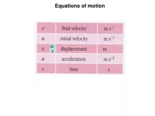
Learn about translational and rotational motion equations for rigid bodies undergoing planar motion. Understand how to analyze problems involving translation and rotation. Discover the scalar equations of motion and their applications.

E N D
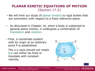
PLANAR KINETIC EQUATIONS OF MOTION (Section 17.2) • We will limit our study of planar kinetics to rigid bodies that are symmetric with respect to a fixed reference plane. • As discussed in Chapter 16, when a body is subjected to general plane motion, it undergoes a combination of translation and rotation. • First, a coordinate system with its origin at an arbitrary point P is established. • The x-y axes should not rotate but can either be fixed or translate with constant velocity.
EQUATIONS OF TRANSLATIONAL MOTION • If a body undergoes translational motion, theequation of motionisF=maG. This can also be written in scalar form as • Fx = m(aG)xand Fy = m(aG)y • In words: the sum of all the external forces acting on the body is equal to the body’s mass times the acceleration of it’s mass center.
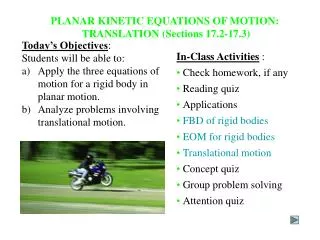
Fx= m(aG)x Fy= m(aG)y MG= 0 EQUATIONS OF MOTION: TRANSLATION (Section 17.3) When a rigid body undergoes only translation, all the particles of the body have the same acceleration so aG= a and a= 0. The equations of motion become: Note that, if it makes the problem easier, the moment equation can be applied about another point instead of the mass center. For example, if point A is chosen, MA= (m aG) d .
EQUATIONS OF MOTION: TRANSLATION (continued) When a rigid body is subjected to curvilinear translation, it is best to use an n-t coordinate system. Then apply the equations of motion, as written below, for n-t coordinates. Fn = m(aG)n Ft = m(aG)t MG= 0 or MB= e[m(aG)t] – h[m(aG)n]
EQUATIONS OF ROTATIONAL MOTION We need to determine the effects caused by the moments of an external force system. The moment about point P can be written as: (riFi)+ Mi=rmaG+IG and Mp= (Mk)p where r= x i + y j and Mp is the resultant moment about P due to all the external forces. The term (Mk)pis called the kinetic moment about point P.
EQUATIONS OF ROTATIONAL MOTION (continued) If point P coincides with the mass center G, this equation reduces to the scalar equation of MG= IG . In words: the resultant (summation) moment about the mass center due to all the external forces is equal to the moment of inertia about G times the angular acceleration of the body. Thus,threeindependent scalar equations of motion may be used to describe the general planar motion of a rigid body. These equations are: Fx = m(aG)x Fy = m(aG)y and MG= IG or Mp = (Mk)p
4.Apply the three equations of motion (one set or the other): Fx= m(aG)x Fy= m(aG)y Fn = m(aG)n Ft = m(aG)t MG= 0 or MP = (Mk)P MG= 0 or MP = (Mk)P PROCEDURE FOR ANALYSIS Problems involving kinetics of a rigid body in only translation should be solved using the following procedure: 1.Establish an (x-y) or (n-t) inertial coordinate system and specify the sense and direction of acceleration of the mass center, aG. 2.Draw a FBD and kinetic diagram showing all external forces, couples and the inertia forces and couples. 3.Identify the unknowns. 5.Remember, friction forces always act on the body opposing the motion of the body.
EQUATIONS OF MOTION: ROTATION ABOUT A FIXED AXIS (Section 17.4) When a rigid body rotates about a fixed axis perpendicular to the plane of the body at point O, the body’s center of gravity G moves in a circular path of radius rG. Thus, the acceleration of point G can be represented by a tangential component (aG)t = rG aand a normal component (aG)n = rG w2. Since the body experiences an angular acceleration, its inertia creates a moment of magnitude, Ig a, equal to the moment of the external forces about point G. Thus, the scalar equations of motion can be stated as: Fn = m (aG)n = m rGw2 Ft = m (aG)t = m rGa MG = IG a
EQUATIONS OF MOTION (continued) Note that the MGmoment equation may be replaced by a moment summation about any arbitrary point. Summing the moment about the center of rotation O yields MO = IGa + rGm (aG) t = [IG + m(rG)2] a From the parallel axis theorem, IO = IG + m(rG)2, therefore the term in parentheses represents IO. Consequently, we can write the threeequations of motion for the body as: Fn = m (aG)n = m rGw2 Ft = m (aG)t = m rGa MO = IO a
PROCEDURE FOR ANALYSIS Problems involving the kinetics of a rigid body rotating about a fixed axis can be solved using the following process. 1.Establish an inertial coordinate system and specify the sign and direction of (aG)n and (aG)t. 2.Draw a free-body diagram accounting for all external forces and couples. Show the resulting inertia forces and couple (typicallyon a separate kinetic diagram). 3.Compute the mass moment of inertia IG or IO. 4.Write the three equations of motion and identify the unknowns. Solve for the unknowns. 5.Use kinematics if there are more than three unknowns (since the equations of motion allow for only three unknowns).
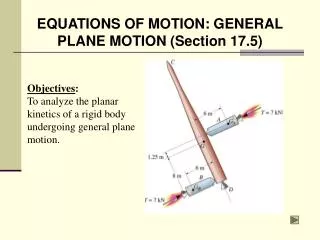
Using an x-y inertial coordinate system, the scalar equations of motions about the center of mass, G, may be written as: Fx = m (aG)x Fy = m (aG)y MG = IG a EQUATIONS OF MOTION: GENERAL PLANE MOTION (Section 17.5) When a rigid body is subjected to external forces and couple-moments, it can undergo both translational motion and rotational motion. This combination is called general plane motion.
EQUATIONS OF MOTION: GENERAL PLANE MOTION (continued) Sometimes, it may be convenient to write the moment equation about a point P, rather than G. Then the equations of motion are written as follows: Fx = m (aG)x Fy = m (aG)y MP = (Mk)P In this case, (Mk )P represents the sum of the moments of IGa and maGabout point P.
FRICTIONAL ROLLING PROBLEMS When analyzing the rolling motion of wheels, cylinders, or disks, it may not be known if the body rolls without slipping or if it slips/slides as it rolls. For example, consider a disk with mass m and radius r, subjected to a known force P. The equations of motion will be: Fx = m(aG)x P F = m aG Fy = m(aG)y N mg = 0 MG = IGa F r = IG a There are4 unknowns (F, N, a , and aG) in these three equations.
FRICTIONAL ROLLING PROBLEMS (continued) Hence, we have to make an assumption to provide another equation. Then, we can solve for the unknowns. The 4th equation can be obtained fromthe slip or non-slip condition of the disk. Case 1: Assume no slipping and use aG=a r as the 4th equation and DO NOT use Ff = sN. After solving, you will need to verify that the assumption was correct by checking if Ff sN. Case 2: Assume slipping and use Ff = kN as the 4th equation. In this case, aG ar.
PROCEDURE FOR ANALYSIS Problems involving the kinetics of a rigid body undergoing general plane motion can be solved using the following procedure. 1.Establish the x-y inertial coordinate system. Draw both the free-body diagram and kinetic diagram for the body. 2.Specify the direction and sense of the acceleration of the mass center, aG, and the angular acceleration aof the body. If necessary,compute the body’s mass moment of inertia IG. 3.If the moment equation Mp= (Mk)p is used, use the kinetic diagram to help visualize the moments developed by the components m(aG)x, m(aG)y, and IGa. 4.Apply the three equations of motion.
PROCEDURE FOR ANALYSIS (continued) 5.Identify the unknowns. If necessary (i.e., there are four unknowns), make your slip-no slip assumption (typically no slipping, or the use of aG=ar, is assumed first). 6.Use kinematic equations as necessary to complete the solution. 7.If a slip-no slip assumption was made, check its validity!!! Key points to consider: 1. Be consistent in using the assumed directions. The direction of aGmust be consistent with a. 2. If Ff = kN is used, Ff must oppose the motion. As a test, assume no friction and observe the resulting motion. This may help visualize the correct direction of Ff.
MASS MOMENT OF INERTIA Consider a rigid body with a center of mass at G. It is free to rotate about the z axis, which passes through G. Now, if we apply a torque T about the z axis to the body, the body begins to rotate with an angular acceleration of . T and are related by the equation T = I . In this equation, I is the mass moment of inertia (MMI)about the z axis. The MMI of a body is a property that measures the resistance of the body to angular acceleration. The MMI is often used when analyzing rotational motion.
MASS MOMENT OF INERTIA (continued) Consider a rigid body and the arbitrary axis P shown in the figure. The MMI about the P axis is defined as I = m r2 dm,where r, the “moment arm,” is the perpendicular distance from the axis to the arbitrary element dm. The mass moment of inertia is always a positive quantity and has a unit of kg · m2or slug · ft2.
MASS MOMENT OF INERTIA (continued) The figures below show the mass moment of inertia formulations for two shapes commonly used when working with three dimensional bodies. These shapes are often used as the differential element being integrated over an entire body.
PROCEDURE FOR ANALYSIS When using direct integration, only symmetric bodies having surfaces generated by revolving a curve about an axis will be considered here. • Shell element • If a shell element having a height z, radius r = y, and thickness dy is chosen for integration, then the volume element is dV = (2py)(z)dy. • This element may be used to find the moment of inertia Iz since the entire element, due to its thinness, lies at the same perpendicular distance y from the z-axis. • Disk element • If a disk element having a radius y and a thickness dz is chosen for integration, then the volume dV = (py2)dz. • Using the moment of inertia of the disk element, we can integrate to determine the moment of inertia of the entire body.
PARALLEL-AXIS THEOREM If the mass moment of inertia of a body about an axis passing through the body’s mass center is known, then the moment of inertia about any other parallel axis may be determined by using the parallel axis theorem, I = IG + md2 where IG = mass moment of inertia about the body’s mass center m = mass of the body d = perpendicular distance between the parallel axes
Radius of Gyration The mass moment of inertia of a body about a specific axis can be defined using the radius of gyration (k). The radius of gyration has units of length and is a measure of the distribution of the body’s mass about the axis at which the moment of inertia is defined. I = m k2 or k = (I/m) RADIUS OF GYRATION AND COMPOSITE BODIES Composite Bodies If a body is constructed of a number of simple shapes, such as disks, spheres, or rods, the mass moment of inertia of the body about any axis can be determined by algebraicallyadding together all the mass moments of inertia, found about the same axis, of the different shapes.
KINETIC ENERGY, WORK, PRINCIPLE OF WORK AND ENERGY KINETIC ENERGY (18.1) The kinetic energy of a rigid body can be expressed as the sum of its translational and rotational kinetic energies. In equation form, a body in general plane motion has kinetic energy given by: T = 1/2 m (vG)2 + 1/2 IG w2 Several simplifications can occur. 1. Pure Translation: When a rigid body is subjected to only curvilinear or rectilinear translation, the rotational kinetic energy is zero (w= 0). Therefore, T = 1/2 m (vG)2
KINETIC ENERGY (continued) 2.Pure Rotation: When a rigid body is rotating about a fixed axis passing through point O, the body has both translational and rotational kinetic energy. Thus, T = 0.5 m (vG)2 + 0.5 IG w2 Since vG = rGw, we can express the kinetic energy of the body as: T = 0.5 [ IG + m(rG)2 ] w2 = 0.5 IO w2 If the rotation occurs about the mass center, G, then what is the value of vG? In this case, the velocity of the mass center is equal to zero. So the kinetic energy equation reduces to: T = 0.5 IG w2
Recall that the work done by a force can be written as: UF = F•dr= (F cos q ) ds. When the force is constant, this equation reduces to UFc = (Fc cos q )s where Fccosq represents the component of the force acting in the direction of the displacement, s. s THE WORK OF A FORCE (Section 18.2) Work of a weight: As before, the work can be expressed as Uw = -WDy. Remember, if the force and movement are in the same direction, the work is positive. Work of a spring force: For a linear spring, the work is: Us = -0.5k[(s2)2 – (s1)2]
FORCES THAT DO NO WORK There are some external forces that do no work. For instance, reactions at fixed supports do no work because the displacement at their point of application is zero. Normal forces and friction forces acting on bodies as they roll without slipping over a rough surface also do no work since there is no instantaneous displacement of the point in contact with ground (it is an instant center, IC). Internal forces do no work because they always act in equal and opposite pairs. Thus, the sum of their work is zero.
If the body rotates through an angular displacement dq, the work of the couple moment, M, is: q2 ò = UM M dq q1 THE WORK OF A COUPLE (Section 18.3) When a body subjected to a couple experiences general plane motion, the two couple forces do work only when the body undergoes rotation. If the couple moment, M, is constant, then UM = M (q2 –q1) The work is positive if M and (q2 – q1) are in the same direction.
PRINCIPLE OF WORK AND ENERGY (Section 18.4) Recall the statement of the principle of work and energy used earlier: T1 + SU1-2 = T2 In the case of general plane motion, this equation states that the sum of the initial kinetic energy (both translational and rotational) and the work done by all external forces and couple moments equals the body’s final kinetic energy (translational and rotational). This equation is a scalar equation. It can be applied to a system of rigid bodies by summing contributions from all bodies.
CONSERVATION OF ENERGY (Section 18.5) The conservation of energy theorem is a “simpler” energy method (recall that the principle of work and energy is also an energy method) for solving problems. Once again, the problem parameter of distance is a key indicator for when conservation of energy is a good method to solve a problem. If it is appropriate for the problem, conservation of energy is easier to use than the principle of work and energy. This is because the calculation of the work of a conservative force is simpler. But, what makes a force conservative?
CONSERVATIVE FORCES A force F is conservativeif the work done by the force is independent of the path. In this case, the work depends only on the initial and final positions of the object with the path between the positions of no consequence. Typical conservative forces encountered in dynamics are gravitational forces (i.e., weight) and elastic forces (i.e., springs). What is a common force that is not conservative?
CONSERVATION OF ENERGY When a rigid body is acted upon by a system of conservative forces, the work done by these forces is conserved. Thus, the sum of kinetic energy and potential energy remains constant. This principle is called conservation of energy and is expressed as: T1 + V1 = T2 + V2 = Constant In other words, as a rigid body moves from one position to another when acted upon by only conservative forces, kinetic energy is converted to potential energy and vice versa.
GRAVITATIONAL POTENTIAL ENERGY The gravitational potential energy of an object is a function of the height of the body’s center of gravity above or below a datum. The gravitational potential energy of a body is found by the equation Vg = W yG Gravitational potential energy is positive when yG is positive, since the weight has the ability to do positive work (why is it positive?) when the body is moved back to the datum.
ELASTIC POTENTIAL ENERGY Spring forces are also conservative forces. The potential energy of a spring force (F = ks) is found by the equation Ve = ½ k s2 Notice that elastic potential energy is always positive.
PROCEDURE FOR ANALYSIS Problems involving velocity, displacement,and conservativeforce systems can be solved using the conservation of energy equation. • Potential energy: Draw two diagrams: one with the body located at its initial position and one at the final position. Compute the potential energy at each position using V = Vg + Ve, where Vg= W yG and Ve = 1/2 k s2. • Kinetic energy: Compute the kinetic energy of the rigid body at each location. Kinetic energy has two components: translational kinetic energy, 1/2m(vG)2,and rotational kinetic energy, 1/2 IG2. • Apply the conservation of energy equation.
LINEAR AND ANGULAR MOMENTUM (Section 19.1) The linear momentum of a rigid body is defined as L = m vG This equation states that the linear momentum vector L has a magnitude equal to (mvG) and a direction defined by vG. The angular momentum of a rigid body is defined as HG = IG w Remember that the direction of HGis perpendicular to the plane of rotation.
LINEAR AND ANGULAR MOMENTUM (continued) Translation. When a rigid body undergoes rectilinear or curvilinear translation, its angular momentum is zero because w = 0. Therefore, L = m vG and HG = 0
LINEAR AND ANGULAR MOMENTUM (continued) Rotation about a fixed axis. When a rigid body is rotating about a fixed axis passing through point O, the body’s linear momentum and angular momentum about G are: L = mvG HG = IGw It is sometimes convenient to compute the angular momentum of the body about the center of rotation O. HO = (rG × mvG) + IG w = IO w
LINEAR AND ANGULAR MOMENTUM (continued) General plane motion. When a rigid body is subjected to general plane motion, both the linear momentum and the angular momentum computed about G are required. L = m vG HG = IG w The angular momentum about point A is HA = IGw + mvG (d)
Linear impulse-linear momentum equation: L1 + Fdt = L2or (mvG)1 + Fdt = (mvG)2 t2 t2 ò ò å å t1 t1 Angular impulse-angular momentum equation: (HG)1 + MGdt = (HG)2or IGw1 + MGdt = IGw2 t2 t2 ò ò å å t1 t1 PRINCIPLE OF IMPULSE AND MOMENTUM (Section 19.2) As in the case of particle motion, the principle of impulse and momentum for a rigid body is developed by combining the equation of motion with kinematics. The resulting equations allow a direct solution to problems involving force, velocity, and time.
PRINCIPLE OF IMPULSE AND MOMENTUM (continued) The previous relations can be represented graphically by drawing the impulse-momentum diagram. To summarize, if motion is occurring in the x-y plane, the linear impulse-linear momentum relation can be applied to the x and y directions and the angular momentum-angular impulse relation is applied about a z-axis passing through any point (i.e., G). Therefore, the principle yields three scalar equations describing the planar motion of the body.
PROCEDURE FOR ANALYSIS •Establish the x, y, z inertial frame of reference. • Draw the impulse-momentum diagrams for the body. •Compute IG, as necessary. •Apply the equations of impulse and momentum (one vector and one scalar or the three scalar equations). •If more than three unknowns are involved, kinematic equations relating the velocity of the mass center G and the angular velocity w should be used to furnish additional equations.
Recall that the linear impulse and momentum relationship is L1 + Fdt = L2 or (mvG)1 + Fdt = (m vG)2 0 0 t2 t2 ò å ò å t1 t1 If the sum of all the linear impulses acting on the rigid body (or a system of rigid bodies) is zero, all the impulse terms are zero. Thus, the linear momentum for a rigid body (or system) is constant, or conserved. So L1 = L2. CONSERVATION OF LINEAR MOMENTUM (Section 19.3) This equation is referred to as the conservation of linear momentum. The conservation of linearmomentum equation can be used if the linear impulses are small or non-impulsive.
0 0 CONSERVATION OF ANGULAR MOMENTUM Similarly, if the sum of all the angular impulses due to external forces acting on the rigid body (or a system of rigid bodies) is zero, all the impulse terms are zero. Thus, angular momentum is conserved (HG)1 + MGdt = (HG)2 or IGw1 + MGdt = IGw2 t2 t2 ò ò å å t1 t1 The resulting equation is referred to as the conservation of angular momentum or (HG)1 = (HG)2 . If the initial condition of the rigid body (or system) is known, conservation of momentum is often used to determine the final linear or angular velocity of a body just after an event occurs.
PROCEDURE FOR ANALYSIS •Establish the x, y, z inertial frame of reference and draw FBDs. •Write the conservation of linear momentum equation. •Write the conservation of angular momentum equation about a fixed point or at the mass center G. •Solve the conservation of linear or angular momentum equations in the appropriate directions. •If the motion is complicated, use of the kinematic equations relating the velocity of the mass center G and the angular velocity w may be necessary.