Download
1 / 25
250 likes | 373 Vues
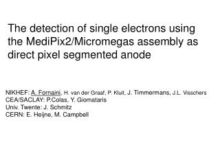
The detection of single electrons using the MediPix2/Micromegas assembly as direct pixel segmented anode. NIKHEF: A. Fornaini , H. van der Graaf, P. Kluit, J. Timmermans, J.L. Visschers CEA/SACLAY: P.Colas, Y. Giomataris Univ. Twente: J. Schmitz CERN: E. Heijne, M. Campbell. Goal.

E N D
The detection of single electrons using the MediPix2/Micromegas assembly as direct pixel segmented anode NIKHEF: A. Fornaini, H. van der Graaf, P. Kluit, J. Timmermans, J.L. Visschers CEA/SACLAY: P.Colas, Y. Giomataris Univ. Twente: J. Schmitz CERN: E. Heijne, M. Campbell
Goal Charged track New readout for a TPC (Time Projection Chamber) GAS Drift field Gas Multiplication System (wires, Gas gain grid, …) Readout Pads (~5 mm2) To readout electronics 2D pads + drift time = 3D information about track Very interesting for high energy physicsexperiments 1
Goal (2) OUR GOAL: - pads (5 mm2) CMOS pixel chip (100 mm x 100 mm) - integrate gas gain grid on the CMOS pixel chip (wafer post processing) - future Linear Collider (or LHC upgrade? Or Babar/Belle?) MANY ADVANTAGES: - Simpler to build: gas gain grid, pads, readout circuitry 1 single element - Better resolution - Single electron detection: dE/dx measurements, d-ray suppression - Large number of readout channels, small pixel size very low hit occupancy Proof-of-principle with the Medipix2 chip 2
The Medipix2 chip • A CMOS chip in .25 mm technology for X-ray imaging • Usually bump-bonded to a semiconductor X-ray sensor • 256 x 256 pixels, area = 1.4 x 1.4 cm2 • Pixel size: 55 mm x 55 mm • Positive or negative input charge (e- or holes collection) • 13-bit counter per pixel • Count rates of 1 MHz/pixel (0.33 GHz/mm2) matrix 14111 mm x 16120 mm periphery Goals: X-ray imaging for many applications (medical, material analysis, synchrotron applications, etc.) 3
Micromegas/Medipix2 prototype TPC: setup Cathode (drift) plane Gas volume Drift space: 15 mm Micromegas Baseplate MediPix2 chip (no sensor) Brass spacer block Printed circuit board Aluminum base plate 4
Micromegas/MPix2 prototype TPC: setup(2) DRIFT (low Electric field) 60 mm pitch 5 mm 35 mm 50 mm Multiplication (high Electric field) Spacer Spacer Anode plane The Medipix2 CMOS chip faces an electric field of 350 V/50 μm = 7 kV/mm !! ~300 V 5
Micromegas/MPix2 prototype TPC: setup(3) Standard Medipix2 chip ~20% metallized surface ~80% insulator Modified Medipix2 chip (lift-off post-processing, Univ. Twente /MESA+) ~80% metallized surface, ~20% insulator 45 x 45 μm2 sens. pixels 6
Micromegas-equipped TPC: results Ar 95 /Isob, 5 (February 2004) Metallized Mpix2 55Fe, 1s 55Fe, 10s 9
Micromegas-equipped TPC: results (2) (February 2004) Metallized Mpix2 Ar 95 /Isob, 5 90Sr, 1s 10
(March-April ‘04) Metallized Mpix2 He80 Isob. 20 (G=5000-10000) No rad. source 15 sec exposure (NO TRIGGER!) Cosmic track 11
(March-April ‘04) Metallized Mpix2 He80 Isob. 80 (G=5000-10000) No rad. source 15 sec exposure Cosmic track 12
(March-April ‘04) Metallized Mpix2 He80 Isob. 80 (G=5000-10000) No rad. source 60 sec. exposure Cosmic track 13
(March-April ‘04) Metallized Mpix2 He80 Isob. 80 (G=5000-10000) No rad. Source 1 sec exposure d-ray! 14
Primary electrons detection • Data set: 6000 cosmics images, • 10-15 sec. acq. time, no trigger • - Noisy pixels eliminated • - Events with MIP selected • (pattern recognition algorithm) • Cuts applied • track xy projection> 50 pixels • more than 5 hits/track • transverse rms < 4 pixels • associated pixels/total • pixels hit > 80% • 164 tracks selected from our data sample 15
Projected lengths (pixels) Fitted e- per mm 16 Fitted e- per mm Fitted clusters per mm
Efficiency for single electrons For each 3D track L: • count number of charge clusters C associated with the track • C/L detected primary electrons/unit length, Nmeasured • primary electrons released by a MIP/unit length: Nexpected (from • literature) e = Nmeasured/Nexpected > 90% with He-based gas mixtures (He/isobuthane 80/20) Single electrons detection efficiency 17
Efficiency: gas gain and pixel threshold e depends on the Mpix2 threshold and gas gain Working point: THR = 3000 e- High efficiency:low threshold, high gainbut a not too high gain is preferable (risk of discharges) so a low threshold is even more important calculation pAval.(n) = 1/G exp(-n/G) To reach higher gains, very high voltages were applied several MPix2 were damaged pthr.(n) = ∫THR 1/G exp(-n/G) Inf. 18
The Moire’ effect • - Bands of lower efficiency • Two perpendicular directions • Periodicity of 12 pixels • Effect less pronounced in • metallized MPix2 chips (image taken with 90Sr source) 19
grid holes Hole above pixel center Hole above 2-4pixels border pixels SOLUTION: integration of gas gain grid on the CMOS chip The Moire’ effect (2) Micromegas: 35 mm diam. holes, 60 mm pitch Medipix2: 55 mm X 55 mm pixels, 55 mm pitch Hole position above the pixel shifts along a column or row Repetition every 60/(60-55) =12 pixels matches the periodicity of the inefficiency bands mismatch! 1) e- pulled to a pixel further away, E field weaker less multiplication +2) charge splits in 2 adjacent pixels 20
Conclusions and future plans • Proof-of principle using Medipix2 was successful: a CMOS • pixel chip can detect electrons in a gas multiplication system! Short term goals: data analysis and simulation Medium term goals: add a cosmic rays triggering system (scintillators), beam test at CERN (e-, p, m…) Long term goals: design of a new TimePix pixel CMOS chip for use in a TPC environment, integration of the gas gain grid (Micromegas) on the MPix2 (and then TimePix) by means of wafer post-processing technology. 21
Projected lengths (pixels) Fitted e- per mm Fitted e- per mm Fitted clusters per mm
Efficiency L H D ▬ select tracks whose projection onto the sensitive pixel plane does not cross the boundary of this plane (to avoid ambiguities) ▬ track 3D length L = √(D2+H2) ▬ count number of charge clusters N: N/L gives information on number of primary electrons per unit length detected PDet ▬ comparison with number of electrons released by a MIP in our gas mixture as given by literature (PCalc) gives information about detection efficiency: e = PDet/PCalc > 90% (He based gas mixt.)