Download
1 / 60
600 likes | 964 Vues
ET3380 Principles and Methods of Electric Power Conversion David Morrisson MS,MBA Week 1. CONTENTS. Principles and Methods of Electric Power Conversion Semiconductor Power Switches Supplementary Components and Systems AC-to-DC Converters AC-to-AC Converters DC-to-DC Converters

E N D
ET3380Principles and Methods of Electric Power ConversionDavid Morrisson MS,MBAWeek 1
CONTENTS • Principles and Methods of Electric Power Conversion • Semiconductor Power Switches • Supplementary Components and Systems • AC-to-DC Converters • AC-to-AC Converters • DC-to-DC Converters • DC-to-AC Converters • Switching Power Supplies • Power Electronics and Clean Energy
The Basics • Every power grid in the U.S. has a few essential components. • These components include the following: • A source: the power plant • A transmission system • A hub: the substation • A distribution system • A user: the home or business
The Source: The Power Plant • Essentially, there are only a few ways to generate AC electricity. • For the vast majority of electricity in the U.S. a fuel (coal, natural gas, a nuclear reaction) is used to create electricity. • In addition, solar, wind and hydroelectric methods are used to generate electricity.
The Heart: The Steam Turbine • Once a fuel has created sufficient heat, steam is created. • Pressure from the steam is used to rotate the steam turbine. • The turbine has magnets attached to the end. • These magnets rotate within coils, thus generating an AC signal.
ElectricalGeneration: Coal, Natural Gas, & Diesel
Relevant Links • http://www.earthlyissues.com/nuclearplants.htm • http://www.southerncompany.com/learningpower/powerinfo_5.aspx
Transmission and Distribution • Once produced, electricity must be distributed. • The main device used to achieve this is the transformer. • Transformers convert AC voltages. • Step-up transformers convert from low to high voltages. • Step-down transformers convert from high to low voltages.
Transmission and Distribution • Power plant transformers step up voltages to reach substations and are sent at approximately 550kV. • Once at the substation, transformers are used to step down voltages to approximately 13kV. • These 13kV voltages are sent via distribution lines to your neighborhood home or business. • Once in the neighborhood, transformers are used (on poles or set on the ground) to step down the electrical voltage to 120/240.
Transmission and Distribution • From the power plant, via transmission lines to the substation. • From the substation, via distribution lines to the home. • All through the use of the transformer.
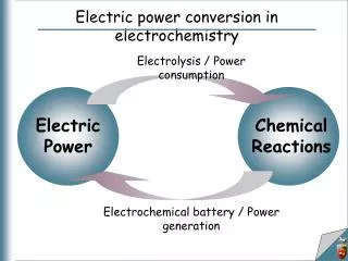
Power Electronics Power electronics is the application of electronic apparatus for the control and conversion of electric power. Also to design, control, computation and integration of nonlinear, time varying energy processing electronic systems The first high power electronic devices were mercury-arc tubes. In modern systems the conversion is performed with semiconductor switching devices such as diodes, thyristors and transistors
Output voltage and current waveforms in the generic rectifier
Output voltage and current waveforms in the generic inverter
Configurations of power electronic converters: (a) current-source(b) voltage-source
Total Harmonic Distortion, or THD • Measurement of the harmonic distortion • Defined as the ratio of the sum of the powers of all harmonic components to the power of the fundamental frequency. • Measurement is most commonly defined as the ratio of the RMS amplitude of a set of higher harmonic frequencies to the RMS amplitude of the first harmonic, or fundamental • Harmonic distortion adds overtones that are whole number multiples of a wave's frequencies
Decomposition of the output voltage waveform in the generic rectifier
Decomposition of the output voltage waveform in the generic inverter
Decomposition of the output current waveform in the generic inverter
Input current waveform and Its fundamental component in the generic inverter
Resistive control schemes: (a) rheostatic control, (b) potentiometric control
Harmonic spectra of output voltage with the firing angle of in: (a) phase-controlled generic rectifier(b) phase-controlled generic AC voltage controller
Output voltage and current waveforms in the generic chopper: switching frequency twice as high as in the previous figure
Fragments of output voltage and current waveforms in a generic PWM ac voltage controller
Output voltage and current waveforms in the single-pulse diode rectifier with an R load
Output voltage and current waveforms in the single-pulse diode rectifier with an RL load
Single-pulse diode rectifier with a free-wheeling diode What are the possible types of loads and what are the effects of each?
Output voltage and current waveforms in the single-pulse diode rectifier with a freewheeling diode and an RL load
Output voltage and current waveforms in the single-pulse diode rectifier with an output capacitor and an RL load
Rectifier Circuits Block diagram of a dc power supply.
Rectifier Circuits Half-wave Rectifier
Rectifier Circuits Full-wave rectifier utilizing a transformer with a center-tapped secondary winding Input and output waveforms.
Rectifier CircuitsBridge Rectifier - V PIV = V s DO Input and output waveforms.
Rectifier Circuits With A Filter Capacitor Voltage and current waveforms in the peak rectifier circuit with CR T. The diode is assumed ideal.