Download
1 / 9
90 likes | 263 Vues
10- Lock Bits, Fuse Bits and Boot Loader. Boot Loader Support – Read-While-Write Self-Programming:

E N D
Boot Loader Support – Read-While-Write Self-Programming: • The Boot Loader Support provides a real Read-While-Write Self-Programming mechanism for downloading and uploading program code by the MCU itself. This feature allows flexible application software updates controlled by the MCU using a Flash-resident Boot Loader program. • The program code within the Boot Loader section has the capability to write into the entire Flash, including the Boot Loader memory. The Boot Loader can thus even modify itself, and it can also erase itself from the code if the feature is not needed anymore. The size of the Boot Loader memory is configurable with Fuses
Memory Programming: • Lock Bits: • Programming and Verification of EEPROM and Flash:
Restrictions for SPM or LPM accessing the Application section:
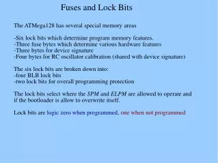
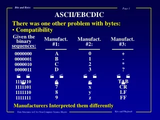
2. Fuse Bits: The ATmega16 has two fuse bytes. Note that the fuses are read as logical zero, “0”, if they are programmed.
Notes: • JTAG (Joint Test Action Group)boundary scan started as a method of testing ICs and their interconnections using a shift register built into the chip so that inputs could be shifted in and the resulting outputs could be shifted out using only four I/O pins (clock, input data, output data, and state machine mode control). This eliminated the need for complex and expensive, bed-of-nails cards for low-speed probing of IC I/O pins. • When used as a debugging tool, an in circuit emulator- which in turn uses JTAG as the transport mechanism - enables a programmer to access an on-chip debug module which is integrated into the CPU, via the JTAG interface. The debug module enables the programmer to debug the software of an embedded system. • OCDEN: On-Chip Debug System Enable
Signature Bytes : All Atmel microcontrollers have a three-byte signature code which identifies the device. This code can be read in both serial and parallel mode, also when the device is locked. The three bytes reside in a separate address space. For the ATmega16 the signature bytes are: 1. $000: $1E (indicates manufactured by Atmel) 2. $001: $94 (indicates 16KB Flash memory) 3. $002: $03 (indicates ATmega16 device when $001 is $94)