Download
1 / 31
310 likes | 473 Vues
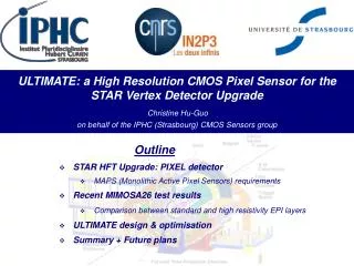
STAR Pixel Detector Sensors and Readout with status of development and prototyping. Pixel Sensor and Electronics Group. LBNL Leo Greiner, Howard Matis Thorsten Stezelberger, Xiangming Sun, Michal Szelezniak, Chinh Vu, Howard Wieman UTA Jo Schambach IPHC Strasburg Marc Winter CMOS group.

E N D
STAR Pixel DetectorSensors and Readoutwith status of development and prototyping
Pixel Sensor and Electronics Group LBNL Leo Greiner, Howard Matis Thorsten Stezelberger, Xiangming Sun, Michal Szelezniak, Chinh Vu, Howard Wieman UTA Jo Schambach IPHC Strasburg Marc Winter CMOS group
Talk Outline The primarily focus of this talk is technical. • Sensor Characteristics. • Sensor and RDO development plan. • Sensor development status. • RDO requirements and design. • Status of RDO prototyping and testing. • Summary.
Monolithic Active Pixel Sensors MAPS pixel cross-section (not to scale) • Standard commercial CMOS technology • Room temperature operation • Sensor and signal processing are integrated in the same silicon wafer • Signal is created in the low-doped epitaxial layer (typically ~10-15 μm) → MIP signal is limited to <1000 electrons • Charge collection is mainly through thermal diffusion (~100 ns), reflective boundaries at p-well and substrate → cluster size is about ~10 pixels (20-30 μm pitch) • 100% fill-factor • Fast readout • Proven thinning to 50 micron
Sensor generation and RDO attributes ADC CDS Data sparsification readout to DAQ Pixel Sensors CDS Disc. Develop sensor chips, 3 generation program (WBS 1.2.2.2) Complementary detector readout digital signals analog signals digital analog MimoSTAR sensors 4 ms integration time 1 2 Phase-1 sensors 640 μs integration time 3 PXL final sensors (Ultimate) < 200 μs integration time Sensor and RDO Development Path
Mimostar Analog Output Sensor Prototypes ADC CDS Data sparsification readout to DAQ Pixel Sensors CDS Disc. Develop sensor chips, 3 generation program (WBS 1.2.2.2) 1 Complementary detector readout digital signals analog signals digital analog MimoSTAR sensors 4 ms integration time Phase-1 sensors 640 μs integration time PXL final sensors (Ultimate) < 200 μs integration time
Mimostar Analog Output Sensor Prototypes Mimostar-2 3 Sensor telescope used at STAR for prototype test in 2007 RHIC run. Description and results are published in: Nuclear Instruments and Methods in Physics Research A 589 (2008) 167–172 • Testing on this generation of sensor is complete. • 3 Sensor telescope used at STAR for prototype test in 2007 RHIC run. • Clean noise environment at STAR. • Interfaces to Trigger and slow controls worked well. • No latch-up events were observed during the run.
Phase-1 Binary Digital Output Sensors ADC CDS Data sparsification readout to DAQ Pixel Sensors CDS Disc. Develop sensor chips, 3 generation program (WBS 1.2.2.2) 2 Complementary detector readout digital signals analog signals digital analog MimoSTAR sensors 4 ms integration time Phase-1 sensors 640 μs integration time PXL final sensors (Ultimate) < 200 μs integration time
Phase-1 Precursor Sensor Prototype Performance 120 GeV π- beam test at CERN • Efficiency > 99%. • Fake hit rate < 10-4. • Meets PXL sensor requirements. CMOS pixel sensor development: a fast readout architecture with integrated zero Suppression – C. Hu, PIXEL 2008
Full Reticle Phase-1 Sensor Status 2 cm x 2 cm Digital output Analog output Phase-1 prototype on testing board. 55Fe spectrum • Phase-1 prototype sensors have been fabricated • Testing is ongoing. • Functionality tests and yield look very good. • Measured ENC is 15 e-. • Beam test to measure MIP efficiency planned for 2010.
PXL Sensor ADC CDS Data sparsification readout to DAQ Pixel Sensors CDS Disc. Develop sensor chips, 3 generation program (WBS 1.2.2.2) 3 Complementary detector readout digital signals analog signals digital analog MimoSTAR sensors 4 ms integration time Phase-1 sensors 640 μs integration time PXL final sensors (Ultimate) < 200 μs integration time
Full reticle PXL Sensor Final PXL Sensor + SUZE – Zero suppression (prototype successfully tested 04/2008) Phase-1 • Overall design is in progress and nearly complete. • 18.4 µm pixels have been chosen for enhanced radiation tolerance. • Mimosa-26 (smaller prototype sensor) under test in Strasbourg, initial results look good.
RDO Requirements and Design Develop readout electronics (WBS 1.2.2.5) • Triggered detector system fitting into existing STAR infrastructure (Trigger, DAQ, etc.) • Deliver full frame events to STAR DAQ for event building at approximately the same rate as the TPC (1 kHz for DAQ1000). • Have live time characteristics such that the Pixel detector is live whenever the TPC is live. • Reduce the total data rate of the PXL detector to a manageable level (< TPC rate of ~1MB / event). • Contain additional functionality for full sensor characterization including production probe testing.
PXL RDO Basic Unit Develop readout electronics (WBS 1.2.2.5) 2m 6m RDO PC 100m • 4 ladders per sector • 1 Mass Termination Board (MTB) per sector • 1 sector per RDO board • 10 RDO boards in the PXL system
Functional Data Path – One Ladder buffer buffer Develop readout electronics (WBS 1.2.2.5) 10 sensors 1 Ladder JTAG, CLK, CTL, markers LU protected power Digital hit data • After power-on and configuration, the sensors are run continuously. • Triggering is handled in the next stage of the RDO.
Functional Data Path – Phase-1 Highly Parallel FPGA based RDO system • 40 sensor outputs/ladder • Each received trigger enables an event buffer for one frame. • The system is dead-time free up to the hardware limit of the number of buffers.
Functional Data Path – PXL Sensor Highly Parallel FPGA based RDO system • 20 sensor outputs/ladder • Same hardware with reconfigured firmware • Each received trigger enables an event buffer for one frame. • Triggered event boundaries are determined by data order.
Parameters and Data Rates PXL System • Data rate to storage = 199 MB/sec (1kHz trigger) • 199kB / event • Meets data rate requirement. • Meets data volume requirement.
LVDS Data Path Testing at 160 MHz http://rnc.lbl.gov/hft/hardware/docs/LVDS/LVDS_test_report_1.pdf 42 AWG wires Ladder mock-up with 1-to-4 LVDS fanout buffers Mass termination board + LU monitoring 24 AWG wires 2 ns eye pattern opening for 1 m 42 AWG cables at 200 MHz Virtex-5 based RDO system with DDL link to PC • Data Path Architecture Validated • Measured BER (bit error rate) of < 10-14
Prototyping Status – Sensor RDO Cables Develop flex PC readout cable (WBS 1.2.2.3) Preliminary Design: Hybrid Copper / Aluminum conductor flex cable Side view (exaggerated vertical scale) • Status • Defined signal paths • Schematic entry complete for preliminary FR-4 test version. • Cable • 4 step development process. • Al traces in low mass region. • Radiation Length ~ 0.073% • Al based cable meets X0 requirement. Low mass region calculated X0 for Al conductor = 0.073 % Low mass region calculated X0 for Cu conductor = 0.232 % http://rnc.lbl.gov/hft/hardware/docs/Phase1/Development_PXL_flex_cable.doc
Prototyping Status – MTB and RDO Boards Mass Termination Board LU protected power regulation board Mass Termination Board LU protected power regulation board • Status • Prototype in hand. • Testing in progress. RDO Board(s) Xilinx VIRTEX-5 development board Mated to a custom readout board. • Status • 3 Prototypes in hand. • Firmware, hardware and software are working for individual sensor testing. • Prototype System is in the advanced stages of testing and working well.
Summary • We have a well advanced sensor and RDO development plan with our collaborators at IPHC. • Analog output sensors have been used successfully in beam at STAR. The noise environment and interfaces to STAR infrastructure seem to be understood. • First generation digital output sensors (Phase-1) have been fabricated and are currently under test. Initial results look promising. • The RDO data path architecture has been validated and the prototype RDO system hardware has been produced. • Prototype RDO firmware and software have been developed and the testing of individual sensors works well. • We will now extend the firmware and software to reading out 10 sensor ladders.
Pixel Detector Characteristics • Two concentric layers at 2.5 & 8 cm radii • 10 sensors/ladder, 4 ladders/module (arm), 10 modules/detector. • MAPS Pixel technology • Sensor spatial resolution < 10 μm • Coverage 2πin φand |η|<1 • Over 400 M pixels on ~0.16 m2 of Silicon • 0.37 % radiation length/layer • MCS limited resolution • Thinned silicon sensors (50 μm thickness) • Air cooled • Sensor power dissipation ~170 mW/cm2 • Quick extraction and detector replacement • Mechanical stability and insertion reproducibility within a 20 μm window • Integration time <200 μs (L=8×1027) • Radiation environment at the level of up to 300k rad/year and 1011 -1012/cm2 Neq /year
Sensor / RDO Overall Detector Requirements • Radiation length of cable + sensor = ~ 0.15 % • Integration time of sensors must keep pile up manageable. (~250 - 350 hits / sensor) • Thermal profile limited by airflow cooling at ~ 170 mW / cm2 • Survive radiation environment at the level (projected) of 300k rad/year and 1011 - 1012/cm2 Neq /year. Optimizations based on these requirements led to the choice of MAPS sensor technology and the sensor development plan and readout design that will be presented.
PXL Detector Design Cabling and cooling infrastructure New beryllium beam pipe (800 µm thick, r = 2.5 cm) Mechanical support with kinematic mounts 2 layers 10 modules 4 ladders/module Detector extraction at one end of the cone Ladder with 10 MAPS sensors (~ 2×2 cm each)
RDO System Design – Physical Layout Sensors / Ladders / Sectors (interaction point) RDO Boards 1-2 m Low mass twisted pair LU Protected Regulators, Mass cable termination Platform 30 m Power Supplies 6 m - twisted pair 30 m 100 m - Fiber optic Control PCs 30 m DAQ Room DAQ PCs (Low Rad Area)
Sensor Generation and RDO Attributes Gen Sensor Sensor RDO Mimostar–2 30 µm pixel, 128 x 128 array 1.7 ms integration time 1 analog output Mimostar–3 30 µm pixel, 320 x 640 array 2.0 ms integration time 2 analog outputs Phase–1 30 µm pixel, 640 x 640 array 640 µs integration time, CDS 4 binary digital outputs PXL Sensor (Ultimate) 18.4 µm pixel, 1024 x 1088 array ≤ 200 µs integration time, CDS, zero suppression 2 digital outputs (addresses) 50 MHz readout clock JTAG interface, control infrastructure ADCs, FPGA CDS & cluster finding zero suppression ≤ 4 sensor simultaneous readout 160 MHz readout clock JTAG interface, control infrastructure zero suppression 40 sensor simultaneous readout 160 MHz readout clock JTAG interface, control infrastructure 400 sensor simultaneous readout (full system) 1 DONE 1 2 PROTOTYPED 3
Sensor / RDO Services (preliminary) 4800 × 42 AWG (TP) 160 × 24 AWG (TP) 1100W (AC) Platform (racks) 10 × USB 2 × TCD (10 TP) 28 × 12 AWG ~30m MTB PP Ladders 180W 300W 6m 240 W RDO Crate 2m 10 × fiber optic cable pair ~100m 1350W (AC) 40 × 0.42” dia. (50 TP cable) 20 × 16 AWG DAQ Room
Radiation Tolerance Risk Mitigation We are putting a program in place to carefully measure the radiation field at STAR. This will improve our current (projected) estimates of the dose received. We have reduced the pixel size to the smallest allowed by our design in the AMS 0.35 technology for our final version of the sensor to enhance the tolerance to radiation damage. The Pixel detector is designed to be replaceable within a 24 hour timeframe. Replacement of a detector due to sensor damage is a feature and we will have a total of 3 physical Pixel detectors. We are currently investigating (with IPHC) different technologies. Graded doping and high resistivity substrate wafers offer the promise of significantly improved collection times and enhanced radiation protection. The results would be available on a timescale to be useful for the final sensor. In addition, IPHC has an active program improving their amplifier designs to be more rad tolerant. Mimosa-22 is expected to reach a tolerance of 1M rad in the next iteration.
Flex Cable Development Hybrid Copper / Aluminum conductor flex cable Side view (exaggerated vertical scale) Top View • 2 layer Al conductor cable in low mass region • 0.004” (100 um) traces and 0.004” (100 um) spaces • 70% fill factor • Conductor thickness in low mass region is 21 um (Cu) or 32 um (Al) • Minimum required conductor trace width 1.325” (33.65 mm) of 46.16 mm available. • Bond wire connection between Al and Cu cable sections. Low mass region calculated X0 for Cu conductor = 0.232 % Low mass region calculated X0 for Al conductor = 0.073 %