Download
1 / 40
400 likes | 414 Vues
This lecture covers the topics of analog transmission, signals, digital transmission, multiplexing, and transmission media in the physical layer of computer communication networks.

E N D
Computer Communication & Networks Lecture # 06 Physical Layer: Analog Transmission Nadeem Majeed Choudhary nadeem.majeed@uettaxila.edu.pk
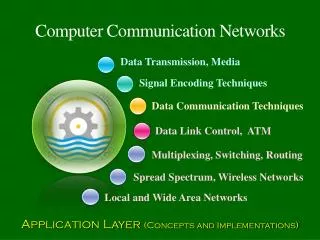
Physical Layer Topics to Cover Signals DigitalTransmission Analog Transmission Multiplexing Transmission Media
Reasons for Conversions • Digital data Digital Signal • Easy and simple to implement • Analog data Digital Signal • Allows the use of digital transmission and switching equipment • Digital data Analog Signal • Allows us of the public telephone system • Allows use of optical fiber • Analog Data Analog Signal • Easy • Telephone system was primarily analog
Data Encoding Techniques Analog Encoding of Digital Information • Phase shift keying • Two binary numbers (0,1) represented by phase shift of the carrier wave • More efficient and noise resistant than FSK • Used up to 9600 on voice grade lines
Data Encoding Techniques Analog Encoding of Digital Information • Techniques can be combined • Common to combine phase shift and amplitude shift • Can get 56kps on a voice grade line • With some techniques called multilevel signaling each signal represents more than one bit • Baud rate = signal changes per second • Bit rate = bits per second
DIGITAL-TO-ANALOG CONVERSION • Digital-to-analog conversion is the process of changing one of the characteristics of an analog signal based on the information in digital data.
Data Rate Vs Signal Rate • Baud rate determines the bandwidth required to send the signal • S = N * 1/r Where S is signal rate, N is data rate and r is number of data elements carried in one signal element.
Note Bit rate is the number of bits per second. Baud rate is the number of signal elements per second. In the analog transmission of digital data, the baud rate is less than or equal to the bit rate.
Example An analog signal carries 4 bits per signal element. If 1000 signal elements are sent per second, find the bit rate. Solution In this case, r = 4, S = 1000, and N is unknown. We can find the value of N from
Example An analog signal has a bit rate of 8000 bps and a baud rate of 1000 baud. How many data elements are carried by each signal element? How many signal elements do we need? Solution In this example, S = 1000, N = 8000, and r and L are unknown. We find first the value of r and then the value of L.
Carrier Signal • In analog signal, the sending device produces a high-frequency signal that acts as a basis for the information signal. This base signal is called the carrier signal or carrier frequency. • Receiving device is tuned to the frequency of the carrier signal that it expects from the sender. • Digital information then modulates the carrier signal by modifying one or more of its characteristics (amplitude, frequency, or phase). This kind of modification is called modulation (or shift keying, and the information signal is called the modulating signal.
Data Encoding Techniques Analog Encoding of Digital Information (cont) • Amplitude shift keying • Two binary numbers (0,1) represented by two different amplitudes of the carrier wave • Rather inefficient • Used up to 1200 bps on voice grade lines • Used to transmit digital data over optical fiber
Bandwidth • Bandwidth of a signal is the total range of frequencies occupied by that signal. • Bandwidth of the signal is centered at carrier frequency fc.
Data Encoding Techniques Analog Encoding of Digital Information (cont) • Frequency shift keying • Two binary numbers (0,1) represented by two different frequencies of the carrier wave • Less susceptible to error than ASK • Used up to 1200bps on voice grade lines • Commonly used for high frequency ( 4 to 30mhz) radio
Analog-to-Analog • Analog-to-analog conversion is the representation of analog information by an analog signal. One may ask why we need to modulate an analog signal; it is already analog. Modulation is needed if the medium is bandpass in nature or if only a bandpass channel is available to us.
Bandwidth Utilization Bandwidth utilization is the wise use of available bandwidth to achieve specific goals. Efficiency can be achieved by multiplexing; privacy and anti-jamming can be achieved by spreading.
Multiplexing • Whenever the bandwidth of a medium linking two devices is greater than the bandwidth needs of the devices, the link can be shared. Multiplexing is the set of techniques that allows the simultaneous transmission of multiple signals across a single data link. As data and telecommunications use increases, so does traffic.
FDM is an analog multiplexing technique that combines analog signals.
Example Assume that a voice channel occupies a bandwidth of 4 kHz. We need to combine three voice channels into a link with a bandwidth of 12 kHz, from 20 to 32 kHz. Show the configuration, using the frequency domain. Assume there are no guard bands. Solution We shift (modulate) each of the three voice channels to a different bandwidth. We use the 20- to 24-kHz bandwidth for the first channel, the 24- to 28-kHz bandwidth for the second channel, and the 28- to 32-kHz bandwidth for the third one.
Time Division Multiplexing TDM is a digital multiplexing technique for combining several low-rate channels into one high-rate one.
Spread Spectrum • Spread Spectrum is a means of transmission in which the data sequence occupies a bandwidth in excess of the minimum bandwidth necessary to send it. • Effectively the signal is mapped to a higher dimension signal space • Signal spreading is done before transmission by using a spreading sequence. The same sequence is used at the receiver to retrieve the signal • Spread Spectrum is most effective against interference (intentional or non-intentional) with fixed energy. • Main commercial applications in wireless and GPS. • Two techniques to spread the spectrum : FHSS, DSSS
DSSS • In direct sequence spread spectrum we use a code of n bits to represent each bit. • Barker sequence is used as spreading code in which n= 11 • So, if signal is N then rate of spread signal is 11N
FHSS • Pseudorandom code generator creates a k-bit pattern for every hopping period. Frequency table uses that pattern to find the frequency to be used and passes it to frequency synthesizer. • Carrier signal is created by frequency synthesizer.
Readings • Chapter 5 (B.A Forouzan) • Section 5.1, 5.2