Beam Line Status
Beam Line Status. Topics to be Addressed. 4. 4. COBRA End-Cap & Insertion + Drive System Status. 3. 3. COBRA/BTS Fringe Field Beam alignment influence. Degrader Commissioning Run Results. 1. 2. 2. COBRA He-atmosphere. 5. 5. - Beam Test BTS. 6.


Beam Line Status
E N D
Presentation Transcript
Beam Line Status MEG Review Meeting June 2006
Topics to be Addressed 4. 4. COBRA End-Cap & Insertion + Drive System Status 3. 3. COBRA/BTS Fringe Field Beam alignment influence • Degrader • Commissioning Run • Results 1. 2. 2. COBRA He-atmosphere 5. 5. - Beam Test BTS 6. .Target System MEG Review Meeting June 2006
Degrader Run Status • Total 5 weeks planned:Many Problems encountered & several Surprises • However: some interesting facts learned !!! • Goal: • first time measurement of Beam in COBRA with Degrader • System deployed at the centre of BTS • understand misalignment problem seen Dec. 2005 • Complications: • First time 6cm Target E employed during MEG Commissioning time • Lost more than 2 weeks of real beam time 11 days due to accelerator 2 days due to controller problems 3-D scanner 1 day control computer problems BTS 1 day Separator vacuum interlock problems • Measurements stopped 4 last days lost due to interference COBRA stray field with other Users beam lines µSR M3 (LTF, GPS) E3 µCap-Expt. Run Programme SHORTENED Could Not Finish everything !!! MEG Review Meeting June 2006
AHV P AHW AHU µ 1st Surprise: Missing Ratefrom 6 cm Target! R4cm=(0.55±0.05)R6cm (1.8) Measured L. Simons et al (Pions!!!) from geometry alone would expect ~ 0.67 (1.5) EXPECTED Very PROVISIONAL !!! Measured R6cm~ 1.24 R4cm With slits open However: - at 1.8mA 6cm Target ~ 1.1·109 e+/s at 4cm Target ~ 7.7·108 e+/s at factor 1.38 ** Naïve Model could explain missing µ+ rate **: Surface µ+ Target Surface e+ Target Volume Target E 4/6 cm Projected Intensity dist. (surface) Low energy -production X-sections rel. stop density factors back face/side face/front face = 3.3/2.5/1.7 If interpretation Correct 6 cm Target BAD for MEG Don’t gain µ+ have ~ 1.4 more background e+ MEG Review Meeting June 2006
2nd Surprise: Beam Misalignment Cause! • Bfield measurements with triple-axis Tesla meter & BTS showed: • BTS Bfield asymmetry at symmetric distances from axis of max. 10G (below axis) • Equivalent toextra Dipole field • symmetry points above/below axis for equal Bfield ~ 30 cm displaced (therefore • not error in measurement) • Area Floor exhibits Remanence & Hysterisis (remembers if BTS +ve/-ve polarity) • fields very reproducible, max. value on Area Floor • Shows iron under the floor !!! which causes field lines to be diverted & alters the • symmetry of the solenoidal field at a point which is important for focusing • Further field measurements after DC-test – with COBRA & BTS ON !!! • Enquired about Hall floor- plans should exist lay-out for 40t/m2 • 40 cm thick layer of steel reinforced concrete • steel layer ~ 30 cm thick starts about 10 cm down • high-quality steel but NOT STAINLESS !!! MEG Review Meeting June 2006
3rd Surprise: Muons Prematurely Range-out! Expected: 100% transmission to centre COBRA, 50% to ~ end COBRA After degrader ~21 MeV/c entry to COBRA Measured: Mean Range at COBRA z= -900 mm R ~1460 mm He Equiv. 235 µm CH2 Extra Material Thickness TMAT~ 900 mm He Equiv. or 145 µm CH2 OR 9 % Air Contamination Know that air back diffusion via leaks problematic as well as suspect “laminar flow” Mixing! test measurement after DC-Test Measure Range Curve post BTS to test Momentum hypothesis 18MeV/c 100% TMAT 50% R~ 1460 mm He 18 MeV/c in He MEG Review Meeting June 2006
Beam Test Conclusions • more than 2 weeks of real beam time lost mainly due to the accelerator • 6 cm target proved problematic since beam wasn’t as expected & • took time to investigate • possible explanation for lack of increase in µ+ rate from 6 cm Target • if true 6 cm Target No good for MEG signal/noise(e+) bad • magnetic field anomaly found (Iron in floor) causes BTS field asymmetry & beam • misalignment (further investigation needed) • good He circulation crucial for MEG – possible cause of our muons ranging-out • range curve post degrader & BTS should answer this • Need extra Beam Time (4 weeks) with 4 cm Target + Degrader • Only possible after end July (4cm Target) –start 4cm Target unstable + low • Current MEGAPIE • Only possible after COBRA stray field influence on other beams solved • To Not Delay MEG - has to be when End-Caps mounted – however problem • no magnet measuring machine possible therefore NEW APD array Detector • NEEDED – (presented Tokyo Meeting) MEG Review Meeting June 2006
Question of Muons “Ranging-out” MEG Review Meeting June 2006
COBRA He-Atmosphere Measure Profiles @ Centre COBRA X = 11.8 mm Y = 12.0 X0 4mm offset Y0 on axis Rate ~ 8·107 µ+/s at 1.8mA, 6cm Target ~ 64% of muons reach centre !!! Muons Range-out prematurely WHY? Checked • Too much material in beam? • Degrader too thick? • New beam window >190 microns • Mylar • Air contamination in He !!! • Momentum too low? • 6cm Target (transverse offset) ??? • AHW41 Bending magnet • measured momentum spectrum Checked MEG Review Meeting June 2006
Beam Materials & Momentum • Degrader: – 33 measurements per foil made • New Mylar Window: - 16 measurements of • sample of same foil made • Beam Momentum: - Integral & Differential Range Curve • measured post BTS using 50µm & 100 µm • Mylar foils Mylar foils + Holder APD+ Holder MEG Review Meeting June 2006
Momentum Measurement Low threshold High threshold + 45.5 mm Air + 20 µm Al foil • Counts µ only (Landau!) • possible threshold dependence • Counts µ+e • no threshold dependence • Michel MS ~ same for all • measurements Mylar RLL= 355 µm RUL= 389 µm Tµ = (2230 ± 60)keV Pµ = (21.8 ± 0.3)MeV/c 3.8% higher than expected, Possible with 6cm Tg ! Gives lateral shift – p change BEAM MOMENTUM OK !!! MEG Review Meeting June 2006
COBRA He-atmosphere 2 Measurements used as cross-check • TU-1530 He-Monitor (Japan) • Range 0-100% He • accuracy ±1 % • Probe part magnetic • Sonic Gas Monitor SGM (home-made) • Calibrated Range 92-100% He • precision ±0.3 % • microphone + speaker magnetic MEG Review Meeting June 2006
He Monitor Cross Calibration TU-153 3.5% Measured Concn SGM 0.2% Gas Rack (mixer) True He-mixture He TU-153 Monitor needs correction within 92-100% Range of 3.5% Air MEG Review Meeting June 2006
C E D B SGM TU-153 A COBRA He-Measurements TU-153 sample He via inserted tube Sampling points: A: SGM B: z = + 2085 mm C: z = + 705 mm D: z = + 45 mm E: z = - 355 mm Pos Comm Run DC Run B 97% 93% C 96% 92% D 90% 89% E 91% 89% P r o v i s i o n a l 3% to 9% Air 7% to 11% Air • He-gradient, worst US !!! • explains ranging-out of Muons • He gas distribution too simple • Care with final gas system !!! MEG Review Meeting June 2006
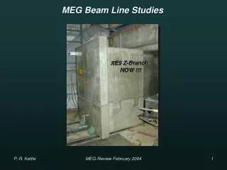
Beam Misalignment & BTS + COBRA Influence MEG Review Meeting June 2006
Beam Misalignment/Fringe Field Problem Initial field measurements during this run with BTS ONLY showed: iron under the floor !!! which causes field lines to be diverted & alters the symmetry of the solenoidal field at a point which is important for focusing Measurements extended to Final BTS settings + COBRA Series of measurements done at US & DS faces of BTS with BTS alone & BTS +COBRA: Asymmetry (beam pipe dia.) BTS alone: US ~ 6 G, C ~ 7G, DS ~ 5G BTS + COBRA: US ~ 6G, C ~ 0.6G, DS ~ 29G MEG Review Meeting June 2006
Aare Aare Bot Top Top DS US Berg Berg Radial BTS Symmetry (No COBRA) BTS Measured radial Symmetry distributions US/DS at beam pipe Diameter I= -200A v. Simple “c-of-g” interpretation Magnetic axis centre US: r=1.6 mm, =292.5° Field Asymmetry ~ 11G DS: r= 4.5 mm, =247.5° FieldAsymmetry ~ 33 G Bot MEG Review Meeting June 2006
Top Bott Radial COBRA Asymmetry BTS+COBRA COBRA Measured radial symmetry distribution US at ~ beam pipe diameter IBTS= -203A, ICOBRA=360/320A v. Simple “c-of-g” interpretation Magnetic axis centre US: r=1.7 mm, =240° asymmetry ~ 55G Problem to be studied by PSI Magnet Group !!! Influence on µ-Beam COBRA Beam Centroid Excursion COBRA centre COBRA centre MEG Review Meeting June 2006
COBRA End-Cap + Insertion & Drive System MEG Review Meeting June 2006
DS US COBRA US End-Cap System US End-Cap schedule Bieri Engineering manufacture costs ~ 55 kCHf delivery to PSI – THIS WEEK (2 weeks late) MEG Review Meeting June 2006
RETRACTED into End-Cap Replace with window Connects to accelerator Beam pipe Gliding support rings NBR Insertion System Detailed FEM study View from Inside COBRA • Gas-tight to He-side CH2/EVAL window • normally connected to motor-driven accelerator • beam tube • frictional hand-drive via electric drill/crank-handle Electric-drill or hand drive MEG Review Meeting June 2006
COBRA DS End-Cap + Insertion & Drive Systems • Complication encountered with DS End-Cap + Insertion & Drive System: • Offer received from Bieri Engineering ~ 200kCHf !!! • successful negotiations with PSI Management for extra money • MEG project raised to priority 1 again – hence PSI workshops can take-over • assembly & testing of complete system … Bieri price now ~ 140 kCHf • Delivery schedule: End-August DS End-Cap (as planned but v. tight) • Mid-September Insertion & Drive System MEG Review Meeting June 2006
BTS -Beam Test MEG Review Meeting June 2006
Single Node SNM Double Node DNM 56 MeV/c 28 MeV/c BTS Pion Beam Test • 1st MEG -beam Studies in 2004: • part of momentum spectrum study • 25-33 MeV/c • dedicated runs at 56 MeV/c & 103 MeV/c • CEX run in E5 at 112 MeV/c Oct. 2004 • ALL BEFORE BTS ARRIVED!!! • Problem: BTS cannot be excited to transmit • Momenta >> 70 MeV/c since • maximum IBTS ~ 270 A • exceeds allowed force on COBRA coils Results -Integral Spot Rates in MHz for 1,8mA Proton Current & 4cm Target E Measured UPSTREAM of BTS position Normalized to Momentum Slit Settings: FS41L/R 250/280 FS43L/R 240/220 Measured US BTS Solution: - should be able to transmit 56 Mev/c particles (2*28 MeV/c) with Good optics 56 MeV/c R = 7.6 ·106 -/s slits open R = 7.2 ·105 -/s slits70/70 MEG Review Meeting June 2006
BTS -Beam Test cont. • BTS test done last week: • Problem encountered – Hamamatsu APD • used for µ+ (no scint. but utilize “Nuclear Counter Effect”) • has no pulse-ht. resolution for - CANNOT DISTINGUISH e- & - • measured at 56 MeV/C & 107 MeV/c with APD & Pill Counter (scintillator) • see pions & electrons with pill-counterBUT CANNOT USE WITH BTS BFIELD • HOWEVER: • COULD TRANSMIT 56 MeV/c PARTICLES as expected BTS Excitation Curve For 56 MeV/c particles Question: What are expected low-energy Pion Beam Rates at centre of COBRA? MEG Review Meeting June 2006
BTS -Beam Test cont. Expected low-energy Pion Beam Rates at centre COBRA for 1.8 mA Proton Beam 4 cm Tg. Taking decay-rate into account Expected Pion Beam Rates Centre COBRA 70 MeV/c ~ 1.6MHz at 1.8mA IPROT • CONCLUSION: • APDs with scintillators needed for Expt. • Cross-System of 13 APDs must be built • before final Commissioning with 4cm Tg • max. -momentum for good optics • ~ 70 MeV/c !!! • expected rate (slits open) 1.6 MHz at COBRA centre MEG Review Meeting June 2006
Target System UCI MEG Review Meeting June 2006
“Target Parking” Insertion Bellows DC structure Target System Mechanical Requirements • Substantial Progress made with Target System since last Review !!! • Supported from DC Support Structure • externally surveyed & introduced with DCs • possibility to move target for End-Cap Insertion System introduction (C-W, LH2,…) • “ target parking” • Mechanically stable & reproducible positioning DC Support Structure Target movement New method of “Parking” using Translation rather than Rotation MEG Review Meeting June 2006
polyester Target System Characteristics • Present Target Characteristics: • Ellipse (210 x 70)mm Polyester foil 175 µm • freely suspended by support pins from a • thin Rohacell support frame at ~22° to axis • (differential expansion) • frame attached by Rohacell support stems • mounted on v. thin movable rods • Driven by pneumatic drive • Current Status UCI: • prototype system • successfully tested • Final System • All parts machined • Assembly & testing about • to start • target foil material & angle • still under study Pneumatic Drive DC Support Rohacell Movement MEG Review Meeting June 2006
DC Support Tube Test Setup UCI Pins on which film is hung Screws for clamping frame Rohacell Frame Prototype Target & Performance • Thin film (~175 micron) target – material to be determined • “soft” polyethylene too difficult to maintain flat • Various polyester, polystyrene, “hard” polyethylene materials possible • Implementation • Target flatness controlled by Rohacell frame – clamping two frames together allows control of flatness • Hanging film between frames allows for differential expansion without deformation of film • Distance between frames controlled by washers at screw locations • Final frame cut precisely with high speed CNC router • Nylon screws/nuts used to reduce mass MEG Review Meeting June 2006
Flatness measured by reflected laser off target surface and measuring reflected angle as laser spot is scanned across target. Z(x,y) = Z(0,0) + ∫ (dz/dx)dx + ∫(dz/dy)dy Target measured to be flat to less than +/-100 microns Prototype Target & Performance cont. Target Size Study Measured 45° target 88% stops Slanted target gives “leakage” due to MS Relatively insensitive to vertical size down to 5.7cm Relatively insensitive to length down to 19 cm HOWEVER Thickness of 175 microns required Final Parameters + slope sense still under study MEG Review Meeting June 2006
Schedule • US End-Cap: • Delivery US COBRA End-Cap: end June • US End-Cap preparations mounting PSI workshops 6WD installation after US TC • US End-Cap installation 5WD Beg. Sept. • Target System: • Production End July • Target assembly + installation 2W • DS End-Cap + Insertion & Drive System: • Delivery DS COBRA End-Cap End Aug. – Mid Sept. • Delivery Insertion + Drive System Mid Sept. • DS End-Cap preparations mounting PSI workshops 6WD installation after DS TC • Insertion & Drive Systemmounting + testing PSI workshops 6WD • DS End-Cap + Insertion & Drive System installation 10WD End. Sept. • Beam Commissioning (degrader + 4cm Tg.) • Beam Line setup + survey 5WD post US End-Cap Beg. Sept. • BTS cryo-connections + pump & cool-down 8WD • Beam Commissioning Run 4Weeks Beg. Oct. • Pion Beam Tune CEX 7D (if not during Comm. Run) before LXe Calib. Mid. Dec. MEG Review Meeting June 2006