Download
1 / 24
390 likes | 1.1k Vues
NFPA 13: Installation of Sprinkler Systems. Establishes the requirements for the layout and design of sprinkler systems. Maximum Coverage for a Sprinkler System. Light Hazard: 52,000 square feet Ordinary Hazard: 52,000 square feet Extra Hazard (Pipe Schedule): 25,000 square feet

E N D
NFPA 13: Installation of Sprinkler Systems • Establishes the requirements for the layout and design of sprinkler systems
Maximum Coverage for a Sprinkler System • Light Hazard: 52,000 square feet • Ordinary Hazard: 52,000 square feet • Extra Hazard (Pipe Schedule): 25,000 square feet • Extra Hazard (Hydraulically Calculated): 40,000 square feet
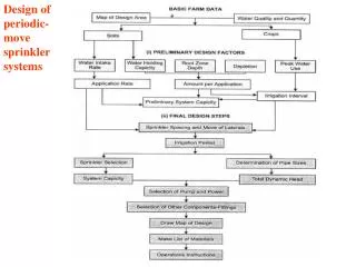
Steps to Completing Sprinkler Layout • Step 1: Classify the building in terms of occupancies • Classify by fire areas of the building • Light Hazard Occupancy – Building or portion that has low quantities of flammable/combustible contents • Ordinary Hazard (Group 1) – Combustibility is low. Quantities of materials is moderate, stockpiles do not exceed 8 feet • Ordinary Hazard (Group 2) – Combustibility is low. Quantities of materials is moderate to high, stockpiles do not exceed 12 feet • Extra Hazard (Group 1) - Quantity and combustibility of materials is very high, dusts, lint present • Extra Hazard (Group 2) Moderate to substantial amounts of flammable liquids are present
Steps to Completing Sprinkler Layout • Step 2: Determine water density from density curve • The Area of Operation from the curve is the maximum area in square feet a fire would expected to spread to under the sprinkler system design criteria • Using this area and building classification, a density is obtained • Using this density multiplied by the area of operation, a water demand in GPM is derived
Sprinkler System Water Demands • With the water demand calculated for the sprinkler system in GPM and the density, the sprinkler system is laid out meeting proper spacing requirements • Ultimately, the GPM per sprinkler head is determined for the heads in the area of operation (area of operation is established furthest from the riser, also referred to as “most remote”)
Number of Heads and Location of Design Area • To determine the number of heads to calculate and the design area, use: • Total Number of Heads = (Design Area)/(Coverage area per sprinkler) • Go to most remote area and identify the correct heads that would have to be hydraulically calculated.
Water Demands at Sprinkler Head • Minimum water demand (Q) at the most remote head must meet (max coverage per head)(density from density curve) • “Most remote” means furthest from the riser in linear distance • Q = (max coverage per head) * (Density from density curve)
Water Pressure Demands • The required water pressure at the most remote head is determined by: • P = (Q / K)2 • P= Pressure in PSI • Q =water flow at the sprinkler head • K = K factor for the particular type of sprinkler head • K Factors give an indication as to the size of the orifice on the head which is related to the gpm that can flow out of the head
Steps to Completing the Sprinkler Layout • Step 3: Using the building classification and design density, determine maximum spacing between sprinkler heads and between branch lines • Also be sure to meet: • Maximum distances between sprinklers • Maximum distances from walls (1/2 maximum distance between sprinklers) • Minimum distance to walls (4 inches) • Minimum distance between sprinklers (6 feet)
Steps to Completing the Sprinkler Layout • Step 4: Verify spacing does not exceed area of protection for each head (A = S X L) • Where Area = Distance between sprinkler heads X distance between branch lines
Office Building Example • An office building is 100’ by 50’ • Classified as a light hazard occupancy • The designer selects a design Area of Operation of 1,500 square feet • This means the hydraulic calculations will ensure the sprinkler system is capable of operating effectively provided the fire is contained to 1,500 square feet at the most remote area of the building
Office Building Example • The riser location is identified • This is the location where the water for the sprinkler system enters the building • Minimum and maximum distances for sprinkler heads and branch lines are determined • The sprinkler system is planned out • Confirm, each head is not required to cover more square footage than its max coverage • Distance between sprinkler heads X Distance between branch lines may not exceed the maximum coverage per head • In our example, 15’ between heads X 15’ between branch lines = 225 square feet which is equal to the max coverage for one head which is 225 square feet
Office Building Example • Number of Heads and Location of Design Area • To determine the number of heads to calculate and the design area, use: • Total Number of Heads = (Design Area)/(Coverage area per sprinkler) • Go to most remote area and identify the correct heads that would have to be hydraulically calculated.
Office Building Example • Example: In a light hazard occupancy with a selected design area of operation of 1,500 square feet: • Total Number of Heads to Calculate = (1,500)/(225) = 6.7 or approx 7 heads • Note: If you calculate your true area of operation for these 7 heads, your building area of protection area is only 1,213 square feet which is more conservative than the 1,500 square feet the 7 heads could be required to protect
Water Demands at Sprinkler Head • Minimum water demand (Q) at the most remote head must meet (max coverage per head)(density from density curve) • Q = (max coverage per head) * (Density from density curve) • Example: For a light hazard occupancy with a design area of protection of 1,500 square feet, using pendant head sprinklers: • Q = (225 square feet) * (.10 gpm/ square foot) = 22.5 gpm minimum for each sprinkler head
Water Demand for the Design Area of Protection • Selected an area of 1,500 square feet • Light Hazard Occupancy • The density on the curve is .10 gpm/square foot • Total water demand for the design Area of Protection is (1,500)*(.10) = 150 gpm • We would hydraulically calculate 7 heads at 22.5 gpm which would produce 157.5 gpm • We would be ensuring our sprinkler system can meet 157.5 gpm which is a higher standard than the 150 gpm
Water Pressure Demands • Using P = (Q / K)2 • P= Pressure in PSI • Q =water flow at the sprinkler head • K = K factor for the particular type of sprinkler head • The designer selected a pendent sprinkler head with a K Factor of 5.6. • The designer determined the minimum water flow for a sprinkler head in this system is 22.5 gpm, therefore: • P = (22.5/5.6)2 = 16.1 psi • The minimum water pressure required at the most remote head in the system is 16.1 psi.
Additional Steps • To ensure the sprinkler system will work properly, hydraulic calculations would be performed to ensure that when all heads in our area of protection are opened at once, there is adequate water pressure (in psi) and water flow (in gpm) at the riser. • If our calculated required pressure is more than the water pressure found at the riser, then changes need to be implemented
Why examine only the most remote area? • The logic of examining only the set number of heads at the most remote portion of the building is as follows: • Keeping pipe diameters and minimum water flow requirements the same throughout the building, because of physics and hydraulics, if the minimum required water pressure and gpm are met at the most remote section of the building, as you move closer to the riser, water pressure and gpm will automatically be greater