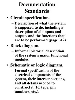
Documentation Standards
Learn how Multiplexers (MUX) function in logic design with detailed diagrams and examples, including how to implement complex logic functions using MUX configurations effectively.


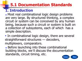
Documentation Standards
E N D
Presentation Transcript
Documentation Standards • Block diagrams first step in hierarchical design • Schematic diagrams • Timing diagrams • Circuit descriptions
Documentation standard Block Diagram
Schematic diagrams • Details of component inputs, outputs, and interconnections • Reference designators • Title blocks • Names for all signals • Page-to-page connectors
8 8 8 8 (warmer + cooler) Wake Period Input keys Digit1 Digit0 Error_Key1 To BCD calculator Error_Key0 To Error Display Select one of Mux From BCD calculator Display D1 D0 Block Diagram For Wake
I. Using MUX to Implement logic function • A multiplex (Data selector) is a CLN module with: • 2n data inputs • n control inputs • 1 output Depending on the control inputs, the multiplexer connects one of the inputs to the output line. • Block diagram of an 4-to-1 multiplexer: I0 I1 I2 I3 D0 D1 D2 D3 Y’ Data inputs 4-to-1 MUX Y C1 C0 Data select
I. Using MUX to Implement logic function Circuit of an 4-to-1 multiplexer D0 C1’C0’D0 D1 Y’ C1’C0D1 OR Y D2 C1C0’D2 D3 C1C0D3 May add an enable signal E C1 C0
I0 I1 I2 I3 I4 I5 I6 I7 D0 D1 D2 D3 D4 D5 D6 D7 Output 8-to-1 MUX Data inputs C2 C1 C0 Data select I. Using MUX to Implement logic function Block diagram of an 8-to-1 multiplexer:
I. Using MUX to Implement logic function Circuit of an 8-to-1 mulmtiplexer
I. Using MUX to Implement logic function Truth table of an 8-to-1 mulmtiplexer
I. Using MUX to Implement logic function Example of design A 2n input lines and n selection lines MUX may be used to realize any function of (n+1) variables Example Use an 8-to-1 MUX to realize the following function of 4 variables F( A,B,C,D) = (0,2,4,5,6,8,10,13) = A’B’C’D’ + A’B’CD’ + A’BC’D’ + A’BC’D + A’BCD’ + AB’C’D’ + AB’CD’ + ABC’D Solution Use the variables A, B, C as the control (selection) inputs and use the remaining variable D to determine the input lines. Rewrite F to to determine a factor for each input combination ABC: F( A,B,C,D) = A’B’C’D’ + A’B’CD’ + A’BC’(D’ + D) + A’BCD’ + AB’C’D’ + AB’CD’ + ABC’D + ABC (0)
I. Using 8-to-1 MUX to Implement logic function Example Solution (Continued ….) F( A,B,C,D) = A’B’C’D’ + A’B’CD’ + A’BC’(D’ + D) + A’BCD’ + AB’C’D’ + AB’CD’ + ABC’D + ABC (0) So the input to the 8-to-1 MUX are given by : I0=D’, I1=D’, I2=1, I3=D’, I4=D’, I5=D’, I6=D, I7=0 1 D’ D’ 1 D’ D’ D’ D 0 D0 D1 D2 D3 D4 D5 D6 D7 F(A,B,C,D) 8-to-1 MUX C2 C1 C0 A B C
I. Using 8-to-1 MUX to Implement logic function Example Same function F(A,B,C,D) Use BCD as the selection (control ) lines F( A,B,C,D) = (0,2,4,5,6,8,10,13) = A’B’C’D’ + A’B’CD’ + A’BC’D’ + A’BC’D + A’BCD’ + AB’C’D’ + AB’CD’ + ABC’D = B’C’D’ ( ) + B’C’D ( ) + B’CD’ ( ) + B’CD ( ) + BC’D’ ( ) + BC’D ( ) + BCD’ ( ) + BCD ( ) = B’C’D’ ( A+A’ ) + B’C’D ( 0 ) + B’CD’ (A’ + A) + B’CD ( 0 ) + BC’D’ ( A’) + BC’D ( A’+A ) + BCD’ ( A’ ) + BCD ( 0 ) 1 1 1
I. Using 8-to-1 MUX to Implement logic function Example 1 0 1 0 A’ 1 A’ 0 D0 D1 D2 D3 D4 D5 D6 D7 F(A,B,C,D) 8-to-1 MUX C2 C1 C0 B C D • Exercise • Repeat using as selection lines: • A, C, D • A, B, D
I. Using 4-to-1 MUX to Implement logic function Example F(A,B,C,D) = (3,4,8,9,10,13,14,15) = A’B’CD + A’BC’D’ + AB’C’D’ + AB’C’D + AB’CD’ + ABC’D + ABCD’ + ABCD Use AB for Selection lines and factor out the various combinations of AB = A’B’ ( CD ) + A’B ( C’D’ ) + AB’( C’D’ + C’D + CD’ ) + AB ( CD’ + CD’ + CD ) = A’B’ ( CD ) + A’B ( C’D’ ) + AB’( C’ + D’ ) + AB ( C + D ) Implement the circuit of the input lines using NAND (or other) gates
C D C’ D’ I. Using 4-to-1 MUX to Implement logic function Example D0 D1 D2 D3 F’ 4-to-1 MUX F C1 C0 A B
II. Decoders • Depending on the control inputs, the multiplexer connects one of the inputs to the output line. • Block diagram of an 4-to-1 multiplexer:
II. Decoders • General decoder structure • Map each input code to one of the output • Typically n inputs, 2n outputs • 2-to-4, 3-to-8, 4-to-16, etc.
Note “x” (don’t care) notation. II. Decoders Binary 2-to-4 decoder
II. Decoders 2-to-4-decoder logic diagram 00 01 10 11
II. Decoders MSI 2-to-4 decoder • Input buffering (less load) • NAND gates (faster) 00 01 10 11
II. Decoders Decoder Symbol
II. Decoders Complete 74x139 Decoder
II. Decoders More decoder symbols
II. Decoders 000 3-to-8 Decoder 001 010 011 100 101 110 111
II. Decoders 74x138 3-to-8-decoder symbol
I. Using decoders to Implement logic function Example: Given F1 = X,Y,Z (1,2,3) and F2 = X,Y,Z (3,5,6,7) Implementation using 3-to-8 Decoder 0 1 2 3 4 5 6 7 X YZ F1 OR F2 OR
I. Using decoders to Implement logic function Example: Given F = X,Y,Z (0,2,3,4,6,7) Implementation using 3-to-8 Decoder We will implement the complement of F and “NOT” the result F’ = m1 + m5 0 1 2 3 4 5 6 7 X YZ F F’ OR
III. Programmable Logic devices Programmable Logic Arrays (PLAs) • Any combinational logic function can be realized as a sum of products. • Idea: Build a large AND-OR array with lots of inputs and product terms, and programmable connections. • n inputs • AND gates have 2n inputs -- true and complement of each variable. • m outputs, driven by large OR gates • Each AND gate is programmably connected to each output’s OR gate. • p AND gates (p<<2n)
Example: 4x3 PLA, 6 product terms III. Programmable Logic devices
Compact representation III. Programmable Logic devices Input programming Output programming
Some product terms III. Programmable Logic devices
IV. Demultiplexer General description • 1-to-2n Demultiplexer has: • 1- input • Multiple outputs • n select lines • Function: Route the single input to the selected output O0 O1 Om . . I Data input . 1-to-2n DEMUX … Select lines m = 2n - 1
IV. Demultiplexer Function table of a 1-to-4 Demux O0 O1 O2 O3 I Data input 1-to-4 DEMUX x y Select lines x y O0 O1O2 O3 0 0 I 0 0 0 O1 = x‘y’I O2 = x’y I O3 = x y’I O4 = x y I 0 1 0 I 0 0 1 0 0 0 I 0 1 1 0 0 0 I
V.Design by Cascading Design an 8-to-1 MUX using 4-to-1 MUX and other gates Cascading MUXes I0 I1 I2 I3 I4 I5 I6 I7 D0 D1 D2 D3 D4 D5 D6 D7 Output 8-to-1 MUX Data inputs En C2 C1 C0 Data select
V.Design by Cascading Design an 8-to-1 MUX using 4-to-1 MUX and other gates Cascading MUXes D0 D1 D2 D3 I0 I1 I2 I3 4-to-1 MUX 0 Output En C1 C0 OR I4 I5 I6 I7 I0 I1 I2 I3 D0 D1 D2 D3 4-to-1 MUX 1 C1 C0 En C2 C1 C0
Note “x” (don’t care) notation. V. Design by cascading Decoders Recall: Decoder with an enable signal En Cascading Decoders
Decoder 2-to-4 1-to-2 d0 d1 d2 d3 d0 d1 i0 i1 i0 En En En i0 d0 d1 0 X 1 0 1 1 0 0 1 0 0 1 V. Design by cascading Decoders Recall: Decoder with an enable signal En Cascading Decoders d0 d1 d2 d3 En i0 i1 0 X X 1 0 0 1 0 1 1 1 0 1 1 1 0 0 0 0 1 0 0 0 0 1 0 0 0 0 1 0 0 0 0 0 d0 d1 i0 En
2-to-4 Decoder 2-to-4 1-to-2 d0 d1 d2 d3 d0 d1 i0 i1 d0’ d1’ i0’ En’ En 1-to-2 d2 d3 d0’ d1’ i0’ En’ En i1 i0 V. Design by cascading Decoders Design of a 2-to-4 decoder using 1-to-2 decoders Cascading Decoders Decoder
2-to-4 Decoder 1-to-2 d0 d1 d0’ d1’ i0’ En’ 1-to-2 d2 d3 d0’ d1’ i0’ En’ En i1 i0 V. Design by cascading Decoders Design of a 2-to-4 decoder using 1-to-2 decoders Cascading Decoders Operation • En enable or disable the decoder • i1=0 enables the top decoder • I1=1 enables the lower decoder
En i1 i0 En i1 i0 En i1 i0 En i1 i0 2-to-4 2-to-4 2-to-4 2-to-4 d0 d1 d2 d3 d0 d1 d2 d3 d0 d1 d2 d3 d0 d1 d2 d3 V. Design by cascading Decoders Design of a 4-to-16 decoder using 2-to-4 decoders Cascading Decoders En i3 i2 i1 i0 En i1 i0 2-to-4 d0 d1 d2 d3 d0 d1 d2 d3 d4 d5 d6 d7 d8 d9 d10 d11 d12 d13 d14 d15
VI.Modular Design • Goal • Use existing components or design subcomponents as building blocks of higher circuit • Types of solutions • Casdading components • Ripple design • Some outpout at level i are used input at the next level (i+1) • Linear cascading of elements
VI.Modular Design Motivations Design of a 2 bits binary adder X Binary adder S Y S = X + Y X=[X1X0], Y=[Y1Y0], S=[S2S1S0] • Two types of design possible: • Brute force approach: Draw a truth table and derive the • expressions of the output variable • Iterative design
VI.Modular Design Example: 2 bits binary adder X1 X0 Y1 Y0 S0 S1 S0 0 0 0 0 0 0 0 0 0 1 0 0 0 1 0 1 0 0 0 1 0 0 1 1 0 0 1 1 • What if we want to do • design a 5 bits adder: • Truth table with 10 variables • Not pratical 0 0 1 0 1 0 0 0 1 0 0 1 0 1 0 1 1 0 1 1 0 1 0 0 0 1 1 1 0 1 0 1 0 0 0 0 1 1 1 0 0 1 1 0 0 1 0 1 0 1 0 1 1 0 1 1 0 1 1 1 1 0 0 1 0 0 1 1 0 1 1 0 1 1 1 1 0 1 1 0 1 1 1 1
VI.Modular Design Iterative design • Identify a basic component: 1-bit adder with carry in • Use the basic component iteratively Basic component • Design of Basic component • Draw its truth table • Design the corresponding circuit Xi 1-bit Full adder Ci Yi Ci-1 Si Iterative design of n-bit adder Xn-2 X0 Yn-2 Y0 Xn-1 Yn-1 1-bit Full adder 1-bit Full adder 1-bit Full adder Cn-3 C-1 Cn-2 … C0 Cn-1 Sn-1 Sn-2 S0
VI.Modular Design Another Example of Modular Design • Design an n-bit comparator to produce the following output F: • F=1 if X > Y • F= 0 otherwise X, Y are n-bit binaries • Basic component C1 • A 1-bit comparator with comparaison result from preceeding • stage • 3 inputs • Xi and Yi bit at stage i, and Fi-1 Result from stage i-1 • 1 output: Fi result of stage I Iterative comparaison of two n-bits X=[Xn-1 …X0] and Y=[Yn-1 …Y0] Xn-1 Xn-2 X1 X0 Cn-1 Cn-2 C1 C0 Fn-1 Fn-2 Fn-3 F1 F0 0 Yn-1 Yn-2 Y1 Y0
VI.Modular Design Another Example of Modular Design Design of the Basic 1-bit Comparator Ci Truth Table K-map XiYi Xi Fi-1 Xi Yi Fi Fi-1 00 01 11 10 Ci 0 0 0 0 Fi Fi-1 1 0 0 0 0 1 Yi 1 0 1 0 1 1 1 1 0 0 1 1 1 1 0 0 0 1 0 1 1 1 1 0 MUX implementation 1 1 1 1 Fi-1 0 4-to-1 Fi MUX 1 Simplified SOP Logic Expression Fi = XiFi-1 + XiYi’ + Yi’Fi-1 Fi-1 Xi Yi