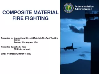
COMPOSITE MATERIAL FIRE FIGHTING
COMPOSITE MATERIAL FIRE FIGHTING. Presented to: International Aircraft Materials Fire Test Working Group K ö ln, Germany Presented by: John C. Hode SRA International Date: Wednesday, June 23, 2010. Composite Aircraft Fire Fighting. THE BIG QUESTION:

COMPOSITE MATERIAL FIRE FIGHTING
E N D
Presentation Transcript
COMPOSITE MATERIAL FIRE FIGHTING Presented to: International Aircraft Materials Fire Test Working Group Köln, Germany Presented by: John C. Hode SRA International Date: Wednesday, June 23, 2010
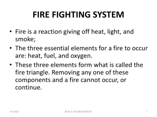
Composite Aircraft Fire Fighting THE BIG QUESTION: Do composite skinned aircraft require more agent to control external fire and facilitate evacuation? • Extinguishment of the body of external fire. • Our question: Will the composite skin continue to burn after the pool fire is extinguished, thereby requiring the fire service to need more extinguishing agent in the initial attack? • Cooling of the composite skin to below 300°F (150°C). • Our question: How fast does the composite skin cool on its own and how much water and foam is needed to cool it faster? • 300°F (150°C) is recommended in the basic ARFF training. • Common aircraft fuels all have auto ignition temperatures above 410°F (210°C).
Representative ScenarioChina Airlines at Japan Naha Airport, August 19, 2007 A leak in the wing fuel tank led to a major external fuel-fed pool fire
Testing in Two Phases Second phase: Determine how much fire agent is needed to extinguish visible fire and cool the material sufficiently to prevent re-ignition. First phase: • Determine if self-sustained combustion or smoldering will occur. • Determine the time to naturally cool below 300°F (150°C) Exposure times of Phase Itests: • 10, 5, 3, 2, & 1 minutes • FAR Part 139 requires first due ARFF to arrive in 3 minutes. • Actual response times can be longer or shorter. Phase I testing of carbon fiber completed.
Test Set-up Ventilation Hood Color Camera FLIR Camera 5 TC’s, center and each corner Color Camera (45° Front view)
Phase I Findings • All tests showed some amount of post-exposure flaming. 1 minute exposures resulted in post-exposure flaming that were sustained well over 1 minute. • Longer exposure burns of the epoxy allowed for glowing combustion of the fibers. Glowing combustion sometimes developed well after exposure • Actual burnthrough never occurred but backside panel temperatures after 10 minute exposures were up to 822°F (442°C). • Temperatures in insulated areas were always several hundred degrees Fahrenheit higher than the panel temperature. 10 minute exposures consistently reached at or above 1200°F (654°C). Average 1367.2°F (741.7°C) • Fiber clusters were released during exposure. Oxidized fibers were noted around the damaged fiber edge where the burner was focused,
Phase I Findings cont. • Panel center, which was open to the air on both sides thereby allowing heat to readily dissipate, took a median of 133 seconds (2 minutes 13 seconds) to cool below 300°F (150°C). • The time for insulated areas to naturally cool below 300°F (150°C) was not sufficiently recorded; however, those areas were above that level for many minutes, well beyond the end of data collection based on trend. • Heavy amounts of combustible gas and smoke flowed from the edges of the panel and in a few cases was ignited by the front-side flame resulting in backside flashover or edge ignition.
Phase I Findings cont. • Wind enhanced glowing combustion and re-ignition. • Radiation between carbon fiber panels can develop extremely high temperatures for sustained periods. • Several tests experienced a mechanical failure of the panel edge. This may be due to the internal pressurization of the panel by epoxy vaporization.
Phase I Findings cont. • Close up of gray oxidized and jagged fiber ends from Test 15
Mechanical Failures • Test 4 panel shown • 7 tests suffered sudden mechanical failures • Failures occurred in 30 seconds on average
Heavy smoke from the backside was sometimes ignited by the front side flame. This was clearly observed during the video review. Here, the ignition of back-side off-gassing happened after the burner was turned off. Off-gas Ignition From Test 18 video
Rear Flashover • Two tests suffered mechanical failures at the bottom edge that allowed high heat to contact and ignite smoke emitting from the bottom edge. • Ignition of bottom edge involved part of the panel face which evolved into flashover of the backside. Test 21 Flashover Test 4 Flashover
Alternate Test Configuration • Measured temperatures in the vicinity of 1750°F (962°C). • Wind in second repetition caused glowing to last 52 seconds longer. • 4:11 without fan • 5:03 with fan
Phase II Testing • Baseline intermediate scale tests will be conducted to see if results from Phase I are repeatable with Phase II test design. • Small scale tests • ASTM E1354 Cone Calorimeter (Additional modeling data) • ASTM E1321 Lateral Flame Spread Testing (Lateral flame spread) • Thermal Decomposition Testing • Intermediate scale tests (agent application to be tested at this level) • Propane fired line burner for fire source. 50 kW/m2 and 200 kW/m2 will be used. • Sample panels will be 4 ft wide by 6 ft tall with protection to avoid edge effects. • Standard aircraft insulation will be installed against backside in some baseline tests.
Thermal Decomposition Testing • Thermal decomposition apparatus used to develop thermal properties for materials • Properties are critical to thermal decomposition modeling • Apparatus provides ability to thermally expose materials in an inert environment
Intermediate-Scale Testing Low Heat Flux Uniform Exposure q"e = 35 – 70 kW/m2 High Heat Flux Uniform Exposure q"e = 70 – 100 kW/m2
Intermediate-Scale Fire Exposure Testing cont. High Heat Flux Localized Exposure q"e = 120 – 200 kW/m2
Agent Application • For now, only water will be used as the extinguishing agent. • Preliminary tests conducted on Oriented Strand Board (OSB) to evaluate burners and agent application method. • Baseline tests will determine the worst case scenario. (insulated vs. un-insulated & heat flux) • Agent applied to worst case combination in data collection tests.
Agent Application Patterns cont. • Tangential spray pattern will be focused to the top of the panel to allow the agent to cascade down the panel. • Conical spray pattern will be focused at the center to cover nearly all of the panel. Test data will contribute to flame spread modeling.
Participation welcome • Soliciting comments and ideas on: • Test configurations and potential ways to improve • Relevant previous testing results and data • Sources for aviation-type carbon fiber composites and FML • Other helpful ideas