Synthesis for Partially Reconfigurable Computing Systems
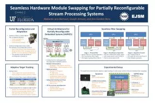
Synthesis for Partially Reconfigurable Computing Systems. Synthesis System Overview. Input Specification (VHDL / C). Translator. High-level Synthesis. Dynamic Reconfiguration Set Generation. Logic Elaboration. Layout Synthesis. Host-side Controller. PARTIALLY RECONFIGURABLE FPGA.

Synthesis for Partially Reconfigurable Computing Systems
E N D
Presentation Transcript
Synthesis System Overview Input Specification (VHDL / C) Translator High-level Synthesis Dynamic Reconfiguration Set Generation Logic Elaboration Layout Synthesis Host-side Controller PARTIALLY RECONFIGURABLE FPGA
Target Architecture Model • Features: • Partially reconfigurable device where a portion • of the device can be reconfigured while the • remaining part is still operational • Target device split into two parts : P1 , P2 • Design is split into sequential blocks and • loaded on the two portions of the device • Reconfiguration of a block is overlapped with • execution of another device P1 P2
Block 1 Block 2 Block 3 Block 4 Block 5 Block 6 Input Specification • Behavior specification in VHDL/C subset • Translated into Intermediate Representation • Intermediate Representation: • Behavior Block Input Format • Single thread of control • Each block performs set of computations • Data transfer through branch interface • Supports control constructs
High-level Synthesis (HLS) Input Specification (Behavior Blocks) RTL Component Library Area / Timing Constraints High-level Synthesis Engine Scheduling Allocation Binding Register - Transfer Level Design (RTL Blocks)
Block 1 RTL Blk 1 Block 2 RTL Blk 2 Block 3 RTL Blk 3 Block 4 RTL Blk 4 Block 5 RTL Blk 5 Block 6 RTL Blk 6 High-level Synthesis (HLS) • Each behavior block in the block graph separately synthesized HLS
RTL Model I/0 Clock Reset Start Finish DESIGN Flags DATAPATH (net-list of components) CONTROLLER (finite state machine) Controls • Glushkovian Model • Components in the datapath implement operations specified in behavior • Controller (FSM) provides necessary controls for execution • HLS generates 4 signals : Clock(in), Reset(in), Start(in), Finish(out)
RTL Blk 1 RTL Blk 2 RTL Blk 1 RTL Blk 2 RTL Blk3|4 RTL Blk 2 RTL Blk 3 RTL Blk 4 RTL Blk3|4 RTL Blk 5 RTL Blk 5 RTL Blk 6 RTL Blk 6 RTL Blk 5 Dynamic Reconfiguration DR • Input: • RTL block graph, with each block having been separately synthesized • Output: • Sequence of reconfiguration sets • Each reconfiguration set has two blocks: one reconfigures, other executes • Intermediate data between blocks stored in board registers
RTL Blk 1 RTL Blk 2 RTL Blk 3 RTL Blk 4 RTL Blk 5 Dynamic Reconfiguration: Example Step1: RTL Block 1 is loaded on the device Step2: RTL Block 1 is executed ; RTL Block 2 is configured Step3: RTL Block 1 completes execution ; RTL Block 3 is reconfigured in place of RTL Block 1; RTL Block 2 is executed Step4: Repeat Steps 2 and 3 until all RTL blocks have been loaded and executed
RTL Blk 1 RTL Blk 2 RTL Blk 3 RTL Blk 4 RTL Blk 5 Latency Improvement • Latency of design without DRSG approach • L1 = (R i + E i) 1 <= i <= n • Latency of design with DRSG approach • L2 = R1 + max(R i+1, E i) 1 <= i <= n • where : • Ri : reconfiguration time of ith block • Ei : execution time of ith block • It is easily seen that L2 <= L1
RTL Blk 1 RTL Blk 2 RTL Blk 3 RTL Blk 4 Handling Conditional Constructs • RTL Block 1 is a conditional block • Either RTL Block2 or RTL Block3 is executed • due to single thread of control • Two approaches to handle conditional • branching • Approach I: host polling • The host waits on the conditional predicate to • evaluate to load the appropriate branch • L1 = R1 + max(R i+1 , E i) +Rj 1 <= i <= n • where Rj : reconfiguration time of the branch that is • executed
RTL Blk 1 RTL Blk 2 RTL Blk 3 RTL Blk 4 Handling Conditional Constructs • Approach II: branch prediction • The host loads one of the branches based on a • user given profile • Latency of the design if the correct branch • was loaded • L1 = R1 + max(R i+1 , E i) 1 <= i <= n • If the wrong branch was loaded, • L2 = R1 + max(R i+1 , E i) +Rj 1 <= i <= n • where Rj : reconfiguration time of the branch • L1 <= L2 , always
Logic Elaboration RTL Component Library Input RTL Specification Logic Elaboration VELAB Elaborated net-list file in EDIF format • Features: • Pre-placed component library to aid layout synthesis • RTL specification obtained form HLS tool ASSERTA • Net-list produced in EDIF format
Layout Synthesis Input Net-list Specification Layout Synthesis XACT6000 FPGA bit-stream • Features: • Manual placement required to ensure place and route using XACT6000 • Replaced blocks are placed in the same location as the blocks they • substitute • Bitmap files produced in cal format
Host-side Controller Bitmap files Reconfiguration Set Sequence Host-side Controller RTR implementation of design • Features: • Manages the partially reconfigurable FPGA device • Loads and executes bitmap files based on the reconfiguration • sequence generated by DRSG phase • Device used is Xilinx 6200
Results : Percentage Configuration time % conf 19.7 11.2 62.8 Design 4x4 2D FFT 4x4 1D DCT 16-tap FIR Total rec. 929 us 1416 us 338 us Overlap 678 us 1161 us 0 us Latency 1276 us 2263 us 538 us Total exec 1025 us 2008 us 200 us • Table presents percentage total time spent only in configuration • using the synthesis flow • The examples show significant improvements in overall latency