Download

1 / 42
680 likes | 1.1k Vues
Arduino Fundamentals Workshop. Brought to you by the Purdue Makers Club Website - http://www.purduemakersclub.com / Facebook - https://www.facebook.com/groups/purduemakersclub/. Trevor Snow & Justin Padinjaremury – Nov, 2013. S o what is a m icrocontroller ?.

E N D
Arduino Fundamentals Workshop Brought to you by the Purdue Makers Club Website - http://www.purduemakersclub.com/ Facebook - https://www.facebook.com/groups/purduemakersclub/ Trevor Snow & Justin Padinjaremury – Nov, 2013
So what is a microcontroller? A microcontroller is a miniature computer typically used for embedded systems. They contain a processor for executing programs, non-volatile (flash) program storage, RAM for variable storage, and various analog and/or digital input/output peripherals. They are everywhere - in cell phones, printers, pacemakers, etc. Government spies put one in my brain!
Projects using microcontrollers 8x8x8 LED Cube Build a drone of your own! Waveform Generator Killbots! Automated Pet Feeder Tons more at http://hackaday.com/category/arduino-hacks/
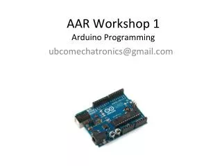
The Arduino Microcontroller “Arduino is an open-source electronics prototyping platform based on flexible, easy-to-use hardware and software.“ Built around Atmel 8-bit AVR microcontroller. Programming software is free. Open source demo board designs may be freely modified for custom designs. Everyone else is doing it… c’mon man, try it!
The Arduino Microcontroller Examples of available boards: Uno Nano Mega 2560 Chip: ATmega328 Chip: ATmega2560 Less $, fewer I/O, small programs More $, more I/O, large programs
The Arduino Microcontroller How do I choose a model board? Few I/O pins needed Uno Lots of I/O pins, large program Mega 2560. Other variants are different form-factors using the ATmega328 (same as UNO). See http://arduino.cc/en/Main/Hardware Consider availability of shield boards. For greater amounts of I/O, greater RAM, faster data processing, consider Raspberry Pi or BeagleBone
Arduino Setup Software: Download Arduino 1.0.5 software at: http://arduino.cc/en/Main/Software Run the installation .exe file. Drivers for the Arduino USB interface should be automatically installed. Let’s get started! Plug your Arduino board into the computer and open the Arduino software.
Arduino Setup Software setup and developing a sketch • Go to Tools, then Board. Select your Arduino model type. • Go to Tools, then Serial Port. Select the COM port the Arduino is connected to (can double check in Device Manager). • Arduino projects are called ”sketches”, which have a ”.ino” extension. • The Arduino language is based on C/C++. Let’s go over what Arduino code looks like and then a simple program.
Arduino Coding Minimal sketch requirements: Go to File, then Examples, then 01: Basics, and select BareMinimum. voidsetup() { //Code that executes once //at power up or reset } void loop() { //Executes repeatedly after //running code in setup() } Need these two functions at minimum. Can be empty. Note: the // forms a comment
Arduino Coding Super simple functional code – blink LED • Every Arduino board has a light-emitting diode (LED) and resistor attached to pin 13. • With pin 13 set LOW (0 volts), the LED is off. • With pin 13 set HIGH (5 volts), LED is on 13 0 V Arduino Board +5 V LED ON Current flow LED OFF
Arduino Coding Super simple functional code – blink LED int led = 13; voidsetup() { pinMode(led,OUTPUT); } void loop() { digitalWrite(led,HIGH); delay(1000); digitalWrite(led,LOW); delay(1000); } Go to File, then Examples, then 01: Basics, and select Blink. Click the button to upload it! Let’s dig deeper on that code… From: http://arduino.cc/en/Tutorial/Blink
Arduino Coding Super simple functional code – blink LED Simple variable with global scope (can be referenced by any function) int led = 13; voidsetup() { pinMode(led,OUTPUT); } void loop() { digitalWrite(led,HIGH); delay(1000); digitalWrite(led,LOW); delay(1000); } From: http://arduino.cc/en/Tutorial/Blink
Arduino Coding Super simple functional code – blink LED pinMode(pin,mode)– pin – pin number to set, mode – INPUT, OUTPUT, or INPUT_PULLUP. NOTE: When a pin is set to OUTPUT, it is capable of sourcing 40 mA of current (out of pin) or sinking 40 mA of current (into pin). Make sure you use resistors and don’t short pins to ground! int led = 13; voidsetup() { pinMode(led,OUTPUT); } void loop() { digitalWrite(led,HIGH); delay(1000); digitalWrite(led,LOW); delay(1000); } From: http://arduino.cc/en/Tutorial/Blink
Arduino Coding Super simple functional code – blink LED digitalWrite(pin,value) – pin – pin number to set, value – HIGH or LOW. If configured for OUTPUT, HIGH sets the pin to 5 V, LOW sets pin to 0 V. If configured for INPUT, HIGH enables internal 20-kΩ pull-up resistor, LOW disables the pull-up resistor. int led = 13; voidsetup() { pinMode(led,OUTPUT); } void loop() { digitalWrite(led,HIGH); delay(1000); digitalWrite(led,LOW); delay(1000); } From: http://arduino.cc/en/Tutorial/Blink
Arduino Coding Super simple functional code – blink LED delay(value) – value – number of milliseconds to pause code execution. NOTE: This stops all code execution, which in some cases is not desired. Instead, use millis(). This returns the number of milliseconds passed since the code started. int led = 13; voidsetup() { pinMode(led,OUTPUT); } void loop() { digitalWrite(led,HIGH); delay(1000); digitalWrite(led,LOW); delay(1000); } t1 = millis(); //more code t2 = millis(); timePassed = t2-t1;
Arduino Coding A quick bit on LEDs: LEDs have a ”turn-on” voltage, somewhat dependent on color of LED LED Current Ultraviolet Infrared 5 V + - LED Voltage + Anode Vd 1 2 3 4 - Cathode Anode Current limiting resistor almost always required – prevents LED and/or driver from blowing up! R Current - +
Arduino Coding A quick bit on LEDs: • Determining current limiting resistor (example): • Given red LED with turn-on voltage ~1.65 V and current rating of 20 mA. First, find voltage drop over resistor: • 5 V - 1.65 V = 3.35 V • Using the equation V = IR (voltage = current * resistance), determine the resistor value: • (3.35 V) / (0.02 A) = 167.5 Ω 5 V + - + Anode Vd - Cathode Anode R Current - + For this LED, use a resistor 168 Ω (ohms) or greater. Generally, using a 1-kΩ resistor works for any LED More detail: http://www.kpsec.freeuk.com/components/led.htm
9 Arduino Board Arduino Coding Hooking up an external LED Can use this for ground, too. Connected bus strip Anode Cathode Connected terminal strip + - 220 Ω Arduino board provides regulated 5 V and 3.3 V outputs If you need both power and ground, use this ground, not one on top side – reduces interference.
Wørkshøppe • Taking it further: • Try modifying the blink example to blink an external LED on your bread board on pin 12, or hook up several LEDs to pins 9-12. • Play with the delay times using the delay() function. Look up how to use the millis() function and use that to generate delays. • Connect multiple LEDs and blink them at different rates or in certain patterns See code references at: http://arduino.cc/en/Reference/HomePage
Arduino Concepts – Digital IN • All digital pins can be configured as an input or an output • If set as input, reading the pin: • Returns 1 or HIGH if above a threshold voltage • Returns 0 or LOW if below a threshold voltage • Threshold has “hysteresis” to limit effect of noise. • Can be used for • Reading buttons or switches • Communicating between digital devices Vin V+t Vt V-t t 1 1 0 0 t
Arduino Concepts – Serial Comms • Serial Communication involves a device digitally writing out a sequence of Highs and Lows (1s & 0s) that correspond to a piece of data, and another device digitally reading it. • Every Arduino has a primary serial port for communicating to and from the PC over the USB line. Timing example of transmitting byte of data serially. • This serial port is used for programming the Arduino and transferring data to and from the computer – this is useful for debugging code. Time to play with buttons and serial ports!
Arduino Concepts – DigitalRead + Serial Circuit 10 kΩ Button up Resistor pulls pin 2 voltage down to ground (LOW) when button is up Go to fritzing.org for the software to make these breadboard diagrams! Button Pressed From: http://arduino.cc/en/Tutorial/DigitalReadSerial
Arduino Coding – DigitalRead + Serial int pushButton = 2; void setup() { Serial.begin(9600); pinMode(pushButton, INPUT); } void loop() { int buttonState= digitalRead(pushButton); Serial.println(buttonState); delay(1); } pinMode(pin,mode) – pin – pin number to set, mode – INPUT, OUTPUT, or INPUT_PULLUP. digitalRead(pin) – pin – pin number to read from. Returns a HIGH (1) or LOW (0) depending on the state of the pin ‘buttonState’ will equal HIGH (1) or LOW (0) based on the value of pin 2
Arduino Coding – DigitalRead + Serial int pushButton = 2; void setup() { Serial.begin(9600); pinMode(pushButton, INPUT); } void loop() { int buttonState= digitalRead(pushButton); Serial.println(buttonState); delay(1); } Serial.begin(speed) speed - transfer rate between the Arduino and the device it is hooked up to, in bits-per-second Call this function to initialize serial communications. Serial.println(val) Prints val to the Terminal, and then starts a new line. valcan be a variable, or text in double-quotes Serial.println(val, format) can be used to specify the output format Serial.print(val, format) can also be used if one doesn’t want to start a new line This code and circuit will repeatedly print the state of the button back to the computer terminal window you opened, with a zero denoting the up-state, and one denoted the down-state.
Arduino Coding – Conditional Statements How do we change code behavior based on inputs, like buttons? IF-ELSE Start Use “if/else” statements! if(condition) { //some code } Button pressed? Turn OFF LED NO If the ‘condition’ statement is true, code in brackets is executed. YES Turn ON LED if(condition) { //some code } else { //some other code } If/else – if ‘condition’ is true, code in first set of brackets is executed, otherwise the code in brackets following ‘else’ is executed.
Arduino Coding – Conditional Statements How do we change code behavior based on inputs, like buttons? Start WHILE Use “while” loop statements! Button NOT pressed? while(condition) { //some code, executes //repeatedly while //‘condition’ is true } //code that executes after //exiting ‘while’ loop Do something YES NO Turn ON LED The ‘condition’ is checked before executing code in brackets. If ‘condition’ is true, code in brackets is executed, then the processor loops back to recheck the ‘condition’. This repeats continuously until the ‘condition’ is false.
Arduino Coding – Conditional Statements Conditional statement operators Examples intx = 5; if(x == 6) { //code not executed }else { //THIS CODE IS EXECUTED } COMPARISON OPERATORS == (equal to) != (not equal to) < (less than) > (greater than) <= (less than or equal to) >= (greater than or equal to) BOOLEAN OPERATORS && (AND) || (OR) ! (NOT) intx = 5; int y = 6; if(x == 6 && y < 10) { //THIS CODE IS EXECUTED } intx = 5; while(x != 7) { x++; //increment x by 1 //THIS CODE IS EXECUTED TWICE }
Wørkshøppe Taking it further: • Use button to control state of LED • When the button is pressed an LED is on • When the button is not pressed an LED is off • Toggle– Look up “switch debouncing” • Make a sketch that toggles an LED on and off, every time the button is pressed. • Make a sketch that displays one of two messages every time the button is pressed. • Cycle • Set up multiple LEDs, where a different one turns on every time you press a button.
Arduino Coding – Analog In • The Arduino contains an Analog to Digital Converter (ADC) which reads a voltage value, and converts it to a number • The Arduino uses a 10-bit ADC, and can read voltages from 0-5V • It will return 0 for 0V and 1023 for 5V
Arduino Coding – Analog In Circuit Potentiometer – 10kΩ
Arduino Coding – Analog In Circuit Let’s look at two of the built-in examples: • First open up ReadAnalogVolatage (under ‘Basics’), upload it, and view the terminal output as you turn the potentiometer. • Then open up AnalogReadSerial, upload it, and view the terminal output as you turn the potentiometer.
Arduino Coding – AnalogIn ReadAnalogVoltage AnalogReadSerial voidsetup(){ Serial.begin(9600); } void loop(){ int sensorValue = analogRead(A0); Serial.println(sensorValue); delay(1); } voidsetup(){ Serial.begin(9600); } void loop(){ int sensorValue = analogRead(A0); float voltage = sensorValue * (5.0 / 1023.0); Serial.println(voltage); } …while this one takes that integer value and recasts it to match the actual voltage level at the input pin. This one reports the digitized analog level as an integer between 0-1023…
Wørkshøppe Taking it further: • Create an indicator for your analog voltage • Hook up 5 LEDs to your Arduino (with appropriate resistors) • Set it up so that the number of LEDs on is proportional to the voltage into your Arduino • 0V -> 0 LEDs on • 1V -> 1 LED on • … 5V -> all 5 LEDs on • Create a sketch that has you cycle through LEDs based on the input voltage • 0V LED0 should be on (all others off) • 1V LED1 should be on (all others off) • …5V LED2 should be on…
Arduino Concepts – ‘Analog’ Out • Just like digital, there is both an analogRead() and analogWrite() • analogWrite()however does not output an analog voltage. Instead it outputs a pulse-width modulated (PWM) signal. • A PWM signal is a square wave signal with a set percentage of it HIGH. • This percentage is called the duty cycle • PWM signals can be filtered to obtain the time-averaged value • 75% duty cycle would be 75% of 5V • 50% duty cycle would be 2.5V
Arduino Coding – Fade int led = 9; int brightness = 0; intfadeAmount = 5; void setup(){ pinMode(led, OUTPUT); } void loop(){ analogWrite(led, brightness); brightness = brightness + fadeAmount; if (brightness == 0 || brightness == 255) { fadeAmount = -fadeAmount ; } delay(30); } Open the Fade sketch from Examples - Basic, and upload it. This code will fade an LED on pin 9. analogWrite(pin, dutyCycle) • pin, Selects the output pin • dutyCycle, (0-255) Sets the duty cycle of PWM output
Arduino Coding – Fade int led = 9; int brightness = 0; intfadeAmount = 5; void setup(){ pinMode(led, OUTPUT); } void loop(){ analogWrite(led, brightness); brightness = brightness + fadeAmount; if (brightness == 0 || brightness == 255) { fadeAmount = -fadeAmount ; } delay(30); } • The code outputs a duty cycle which is proportional to the LED brightness. • The code then increases the brightness. • If the code hits the maximum duty cycle (255), it starts to decrease the brightness. • If it hits the minimum duty cycle (0), it starts to increase the brightness.
Wørkshøppe Taking it further: • Dim an LED with a Potentiometer • Read the analog voltage in from a potentiometer. • Output a duty cycle proportional to the analog voltage – this drives the LED. • You may want to investigate the map() function. • Your system should behave like this: • 0V in --> LED off • 2.5V in --> LED half bright • 5V in --> LED fully bright
State Machines • A useful way to code is to think of your code as a state machine. • A state is a particular set of outputs or behavior. • Whenever you give an input, the state would change in from one state to another, or stay in the same state. • This basic concept is called a state machine: • Have a set of combinations of outputs • Change between the combinations based on what input was given. Really, really simple state diagram
State Machines • Evaluate inputs or events that determines which state to go to. • Set internal variable to the new state index, using transition rules based on input and current state. • Set outputs that correspond to the new state. • The easiest way to implement a state machine in code is with a switch()statement. switch(x) { case 1: //executes if x == 1 break; case 2: //executes if x == 2 break; default: //executes for all other values of x }
Final Wørkshøppe/Hømewørk Ze final challenge - Create a combination lock • Create a three-digit code sequence using integers 0-5. • Using a potentiometer, read in an analog voltage and have it represent integers 0-5. • Indicate this number using external LEDs. • When a button is pressed, the number is recorded. • When three numbers are recorded, indicate if it was the correct or incorrect sequence via an LED or two LEDs.
Where do you go from here? More specifics on programming Atmel AVR chips: http://hackaday.com/2010/10/23/avr-programming-introduction/ Many well thought out tutorials: http://arduino.cc/en/Tutorial/HomePage Inspiration: http://hackaday.com/ http://www.adafruit.com/blog http://www.instructables.com/ Components: http://www.adafruit.com http://www.sparkfun.com