
Uploaded by
vian
15 SLIDES
655 VUES
170LIKES
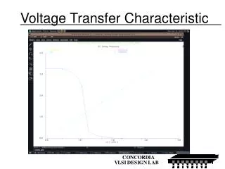
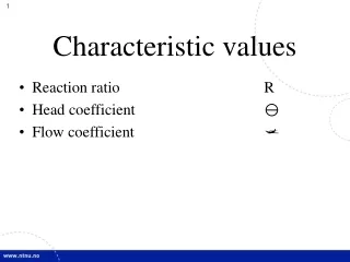
Voltage Transfer Characteristic
DESCRIPTION
Voltage Transfer Characteristic. The simulated Inverter. Inverter layout. Inverter Characterization. VTC of Seven Inverters, WP = WN to WP = 7 WN. The threshold voltage for each of the seven inverters ideal threshold voltage Vth = VDD/2 = 1.65 V. Determination of the optimum VTC.
Download
1 / 15
Télécharger la présentation 
Voltage Transfer Characteristic
An Image/Link below is provided (as is) to download presentation
Download Policy: Content on the Website is provided to you AS IS for your information and personal use and may not be sold / licensed / shared on other websites without getting consent from its author.
Content is provided to you AS IS for your information and personal use only.
Download presentation by click this link.
While downloading, if for some reason you are not able to download a presentation, the publisher may have deleted the file from their server.
During download, if you can't get a presentation, the file might be deleted by the publisher.
E N D
Presentation Transcript
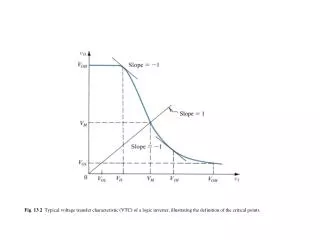
The threshold voltage for each of the seven inverters ideal threshold voltage Vth = VDD/2 = 1.65 V
Optimum VTC Wp=7Wn=Vdd/2 VTC with Vth, VIL, and VIH for Inverter for (WP/WN) = 7
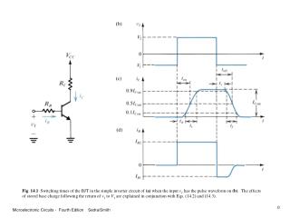
Inverter’s Transient response Input Waveform Output Response
Laying out an inverter The pMOS The nMOS The Inverter


More Related