Download
1 / 34
350 likes | 510 Vues
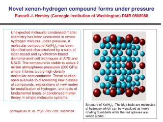
19-PMT Electroluminescent High Pressure Xenon TPC. Azriel Goldschmidt, LBNL. Institutions/People Involved (so far). LBNL: D. Nygren, H. Spieler, A. Goldschmidt, R. Lafever, T. Weber, D. Hogan, J. Reiner + others… LLNL: A. Bernstein, M. Heffner + others… Texas A&M: J. White + students

E N D
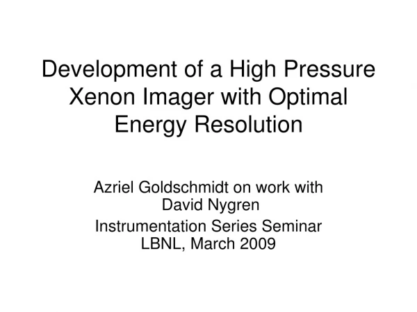
19-PMT Electroluminescent High Pressure Xenon TPC Azriel Goldschmidt, LBNL
Institutions/People Involved (so far) • LBNL: D. Nygren, H. Spieler, A. Goldschmidt, R. Lafever, T. Weber, D. Hogan, J. Reiner + others… • LLNL: A. Bernstein, M. Heffner + others… • Texas A&M: J. White + students • and collaboration with NEXT
Overview • Energy resolution in HPXe • Electroluminescent gain • Goals of 19-PMT (10 liter, 1kg@20Atm) system • Gas System / Cycle • Field Cage / Light Pipe • PMTs/DAQ • Calibration sources / methods / Simulations
Intrinsic energy resolution E/E = 2.35 (FW/Q)1/2 • F Fano factor: F = 0.15 (HPXe) • W Average energy per ion pair: W ~ 25 eV • Q Energy release in decay of 136Xe: ~2500 keV E/E = 2.8 x 10⁻³ FWHM (HPXe) N = Q/W ~100,000 primary electrons N =(FN)1/2~120 electrons rms!
Xenon: Strong dependence of energy resolution on density! Ionization signal only For >0.55 g/cm3, energy resolution deteriorates rapidly
What E-drift is required for best energy resolution? • An important goal of 19-PMT system is to verify/check this dependency 1.3% FWHM whenextrapolated to 2.5 MeV With 50 kV/meter 0.3% FWHM whenextrapolated to 2.5 MeV Would require 400 kV/meter !
Gain and noise Impose a requirement: (noise + fluctuations) 120 e— Need gain G with very low noise/fluctuations! Uncorrelated fluctuations, add in quadrature: • = ((F + G)N)1/2 F constraint due to fixed energy deposit G noise/fluctuations of detection process
Electro-Luminescence (EL) is the key Coimbra seminal work… • Physics process generates ionization signal • Electrons drift in low electric field region • Electrons enter a high electric field region • Electrons gain energy, excite xenon: 8.32 eV • Xenon radiates VUV (175 nm, 7.5 eV) • Electron starts over, gaining energy again • Linear growth of signal with voltage • Photon generation up to ~1000/e, but no ionization • No exponential growth fluctuations are very small (< 1 e- RMS)
Virtues of Electro-Luminescence in HPXe • Linearity of gain versus pressure, HV • Immune to microphonics (level of displacements?) • Absence of positive ion space charge • Absence of ageing, quenching of signal • Isotropic signal dispersion in space • Trigger, energy, and tracking functions accomplished with optical detectors
Fluctuations & Total signal at Q-value Q/W = N = 1 x 10⁵ Uncorrelated fluctuations: = ((F + G)N)1/2 For G ≤ F = 0.15 npe ≥ 10 (per primary electron) Npe 1 x 10⁶ One million photoelectrons! However: Npe is spread out over >100 PMTs and 10 - 100 µs No dynamic range problem
Electroluminescence in 4.5 bar of Xenon Corresponds to 5 x 10⁻³ FWHM When naively extrapolated toQbb of 2.5 MeV (compare with the Fano limited 2.8 x 10⁻³ FWHM best case)
Separated Function TPC with Electroluminescence Readout Plane A - position D. Nygren Readout Plane B - energy Electroluminescent Layer
19 PMT HPXe TPC: 10 liter @ 20 Atm Argon Purge circuit Pressure / Vacuum vessel Xenon purification circuit Graphics by Robin Lafever Goals: 1. E/E resolution (662 keV) 2. explore sensitivity of energy resolution to drift E-field
In this version only light sensing on the “far end” (energy) of the EL plane
Options for Electroluminescence production • Two parallel meshes: • Produces a “too much” light at 20 Atm • Requires ~micron tolerances for gain uniformity • Single wire plane: • EL in region up to ~8R • “Ultra” wire with radius uniformity <1 micronprovides built-in gain uniformity • Light gain ~ 1100*p(Atm)*R(cm) • P=20, R=0.0150, Gain=330 • Light produced “in front” of the wire • Wire displacements? • Other: Wire plane and near field wires…(issues with tolerances and gain uniformity) J. White
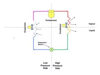
Gas System Turbo pump Vacuum valve High pressure valve GettersSAES MicroTorr MC50SAES MicroTorr MC190 Argon Recirculating pumpPW 2070 Dewar for Xenontransfer to chamber To roughing pump Xenon container &Dewar for Recapture Robin Lafever, LBNL
Gas Cycle • Vacuum pump to ~10-7 Torr • Let Argon in • Re-circulate Argon thru getters and flush • Vacuum pump again • Transfer Xenon by freezing in chamber reservoir • Let warm up and achieve high pressure • Re-circulate Xenon • Perform experiments/calibration/measurements • Recapture Xenon by freezing container
DAQ for 19-PMT system • Total energy measurement requires summing of all channels • Signal duration depends on track orientation (~5 – 100 microseconds) integrate over time bins • Each channel must be calibrated (ADC slope + offset vs. light impinging on PMT) array of calibration LEDs • Digitization must be accurate to single photoelectron (minimum bin determined by ADC channel profile) • Max signal for tracks parallel to luminescent gain plane • Use 100 MS/s 16-bit ADC with 13-bit resolution
Simulation of 662 keV’s on axisTracks and Spatial Distribution 662 keV g’s Thru 0.5’ wall
662 keV g’s Thru 0.5’ wall
Simulation 662 keV gammas on axis • Reflectivity walls 75% • Endcaps do not reflect • EL Gain ~1000 • 15% PMT Q.E. • All topologies • Energy is sum of PEs • Fano factor=0 • ~300,000 PEs/662 keV • 0.7% FWHM (0.4% is just stats) • Widening of resolution is due to radial dependence on the light collection (solid angle)
Diagonal low energy gamma ray source • Simulation with 75% reflectivity on walls • Collimated source inside the pressure vessel • Use time of primary to determine Z and thus Radius 122 keV g photoelectrons 10% Z (cm) Z (cm)
Status of 19-PMT system • HP Vessel: in place, loan from LLNL • Gas System: design nearly complete • Procuring parts (valves, pipe, etc) • Recirculation pump and getters already in • TPC “guts”: design nearly complete • PMT/DAQ: • 24 PMTs , testing starts in ~weeks • Struck digitizers on order
This treatment uses 41-pin Conflat 17156-01-CF 17156-01-CF
HV Grids Field Cage Precision-ground ceramic spacers HV Grids PMT array Ceramic rods HV Grid plane Teflon mount plate Teflon HV Grid supply