Download

1 / 25
360 likes | 2.55k Vues
The application of intermolecular forces in LCD technology. Content. Introduction LCD History Structure of LCD monitor Intermolecular Force Permanent Diople moment Polarization The mechanism of LCD monitor Summary Group member list . Introduction.

E N D
Content • Introduction • LCD History • Structure of LCD monitor • Intermolecular Force • Permanent Diople moment • Polarization • The mechanism of LCD monitor • Summary • Group member list
Introduction • You probably use items containing an LCD (liquid crystal display) every day. They are all around us -- in laptop computers, digital clocks and watches, microwave ovens, CD players and many other electronic devices. LCDs are common because they offer some real advantages over other display technologies. They are thinner and lighter and draw much less power than cathode ray tubes (CRTs). But how much do you know about LCDs technology? • LCDs technology is the application of intermolecular forces. The liquid crystal which have permanent dipole moment line up in the electric field in LCD monitor. By the difference electric current, the LCD will display difference colours by the difference polarization of liquid crystal and the specific structure of the LCD monitor.
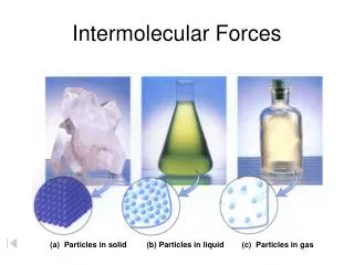
Liquid Crystals Solids act the way they do because their molecules always maintain their orientation and stay in the same position with respect to one another. The molecules in liquids are just the opposite: They can change their orientation and move anywhere in the liquid. But there are some substances that can exist in an odd state that is sort of like a liquid and sort of like a solid. When they are in this state, their molecules tend to maintain their orientation, like the molecules in a solid, but also move around to different positions, like the molecules in a liquid. This means that liquid crystals are neither a solid nor a liquid. That's how they ended up with their seemingly contradictory name. So, do liquid crystals act like solids or liquids or something else? It turns out that liquid crystals are closer to a liquid state than a solid. It takes a fair amount of heat to change a suitable substance from a solid into a liquid crystal, and it only takes a little more heat to turn that same liquid crystal into a real liquid. This explains why liquid crystals are very sensitive to temperature and why they are used to make thermometers and mood rings. It also explains why a laptop computer display may act funny in cold weather or during a hot day at the beach!
LCD History • Today, LCDs are everywhere we look, but they didn't sprout up overnight. It took a long time to get from the discovery of liquid crystals to the multitude of LCD applications we now enjoy. Liquid crystals were first discovered in 1888, by Austrian botanist Friedrich Reinitzer. Reinitzer observed that when he melted a curious cholesterol-like substance (cholesteryl benzoate), it first became a cloudy liquid and then cleared up as its temperature rose. Upon cooling, the liquid turned blue before finally crystallizing. Eighty years passed before RCA made the first experimental LCD in 1968. Since then, LCD manufacturers have steadily developed ingenious variations and improvements on the technology, taking the LCD to amazing levels of technical complexity. And there is every indication that we will continue to enjoy new LCD developments in the future!
Structure of the LCDs monitor The structure of LCD monitor just like a sunglasses. The liquid crystal is placed at the position of the polarizing film and it is placed between two electrodes. After each electrode is a polarization film. Ant the resistant coating is absent in the LCDs structure.
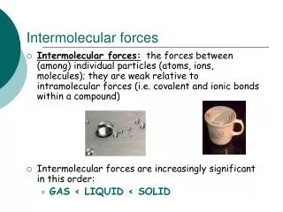
What are Intermolecular Force? • Intermolecular force are weak force holding molecules together • Their strengths are usually in the range of 1 to 40 KJ mol-1 • About 5 to 10% strengh of covalent bond . • Molecules are attracted to each other by intermolecular force • Electrostatic in nature. 2 major types of intermolecular force : • Van der Waals’ force • Hydrogen bond
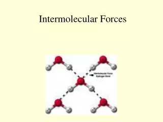
Hydrogen bond • Attraction between a H atom bonded to an electronegative atom and the lone pair e- on another electronegative atom • Strengh is usually 8 to 40KJ mol-1 • Hydrogen bond is stronger than Van Der Waals’ force HF H▬▬F - - - - - H▬▬F Covalent bond Hydrogen bond
Van der Waals’ force • Attractive which exist between all molecules including polar molecules and nonpolar molecules • Strength is usually < 10KJ mol-1 Cl▬▬Cl - - - - - Cl▬▬Cl Cl2 Covalent bond (strong) Van der Waals’ force
Permanent dipole – permanent dipole attractions • Known as the dipole-dipole attraction which exist between all molecules with Permanent dipole moment • Similar to….
Permanent dipole – permanent dipole attractions 2 • The difference in electronegativities between element in a covalent bond produces a certain drgree of polarization. • The electron density is no longer evenly distrbuted between the 2 nuclei. This type of separation of charge produces a permanent dipole monent of the bond • The overall dipole monent of the molecule is the vector sum of the individual dipole moment is non-zero , the molecule has a permanent dipole monent and is said to be a polar molecule
Permanent dipole – permanent dipole attractions 3 • When polar molecules come together , no matter how they orient ,permanent attractive force result : permanent diople attraction or simply the diople-diople attractions. • Note that the molecules cannot come closer than a distance that the electronic repulsion between the molecules are larger than the attraction • At high temperature , the vigorous molecular movement may overcome the diople-diople attraction so that the molecules arrange randomly.At low temperature the molecules align regularly in head-to-tail fashion.
Polarization • Light waves from the sun, or even from an artificial light source such as a light bulb, vibrate and radiate outward in all directions. Whether the light is transmitted, reflected, scattered or refracted, when its vibrations are aligned into one or more planes of direction, the light is said to be polarized. Polarization can occur either naturally or artificially. You can see an example of natural polarization every time you look at a lake. The reflected glare off the surface is the light that does not make it through the "filter" of the water, and is the reason why you often cannot see anything below the surface, even when the water is very clear.
Example of artificial polarization • Polarized filters are most commonly made of a chemical film applied to a transparent plastic or glass surface. The chemical compound used will typically be composed of molecules that naturally align in parallel relation to one another. When applied uniformly to the lens, the molecules create a microscopic filter that absorbs any light matching their alignment. • Most of the glare that causes you to wear sunglasses comes from horizontal surfaces, such as water or a highway. When light strikes a surface, the reflected waves are polarized to match the angle of that surface. So, a highly reflective horizontal surface, such as a lake, will produce a lot of horizontally polarized light. Therefore, the polarized lenses in sunglasses are fixed at an angle that only allows vertically polarized light to enter. You can see this for yourself by putting on a pair of polarized sunglasses and looking at a horizontal reflective surface, like the hood of a car. Slowly tilt your head to the right or left. You will notice that the glare off the surface brightens as you adjust the angle of your view. • A lot of sunglasses advertised as polarizing actually are not. There's a simple test you can perform before you buy them to make sure. Find a reflective surface, and hold the glasses so that you are viewing the surface through one of the lenses. Now slowly rotate the glasses to a 90-degree angle, and see if the reflective glare diminishes or increases. If the sunglasses are polarized, you will see a significant diminishing of the glare.
SINGLE MOLECULE POLARIZATION Following figures are demonstrating this polarisation dependence by means of confocal imaging of single fluorescein molecules randomly distributed on a glass surface. A single molecule shows up as a bright spot in the image. Figures a) and b) show trace and retrace of the same scan area. The linear polarisation orientation of the excitation light was switched between a) vertical to b) horizontal polarisation (yellow arrows). Each polarisation direction selects a different set of molecules depending on the individual orientations of their absorption transition dipoles. Examples are highlighted by boxes, circles and triangles. Note that molecules having an absorption dipole along the optical axis cannot be excited in this set-up.
SINGLE MOLECULE POLARIZATION • Figure c) visualises the polarisation of the fluorescence emission. Shown is the same area as in a) and b) but using circular polarised excitation light instead of linear. Both sets of molecules are now excited. A false colour scale is used (see colour table in upper right corner) to indicate the in-plane orientation of the molecules' individual emission transition dipoles. The colour scale ranges from green (for molecules oriented along the horizontal image direction) via yellow to red (for molecules oriented along the vertical image direction). Additionally, one can observe two other typical single molecule effects in this image: • Molecule A exhibits a dark interval caused by temporal excursion to the triplet state (blinking). • Molecule B bleaches in a digital way while the laser focus is moved over it.
Creating an LCD • An LCD is a device that uses these four facts in a surprising way! To create an LCD, you take two pieces of polarized glass. A special polymer that creates microscopic grooves in the surface is rubbed on the side of the glass that does not have the polarizing film on it. The grooves must be in the same direction as the polarizing film. You then add a coating of nematic liquid crystals to one of the filters. The grooves will cause the first layer of molecules to align with the filter's orientation. Then add the second piece of glass with the polarizing film at a right angle to the first piece. Each successive layer of TN molecules will gradually twist until the uppermost layer is at a 90-degree angle to the bottom, matching the polarized glass filters. • As light strikes the first filter, it is polarized. The molecules in each layer then guide the light they receive to the next layer. As the light passes through the liquid crystal layers, the molecules also change the light's plane of vibration to match their own angle. When the light reaches the far side of the liquid crystal substance, it vibrates at the same angle as the final layer of molecules. If the final layer is matched up with the second polarized glass filter, then the light will pass through. • If we apply an electric charge to liquid crystal molecules, they untwist! When they straighten out, they change the angle of the light passing through them so that it no longer matches the angle of the top polarizing filter. Consequently, no light can pass through that area of the LCD, which makes that area darker than the surrounding areas
Building LCD • Building a simple LCD is easier than you think. Your start with the sandwich of glass and liquid crystals described above and add two transparent electrodes to it. For example, imagine that you want to create the simplest possible LCD with just a single rectangular electrode on it. The layers would look like this: • The LCD needed to do this job is very basic. It has a mirror (A) in back, which makes it reflective. Then, we add a piece of glass (B) with a polarizing film on the bottom side, and a common electrode plane (C) made of indium-tin oxide on top. A common electrode plane covers the entire area of the LCD. Above that is the layer of liquid crystal substance (D). Next comes another piece of glass (E) with an electrode in the shape of the rectangle on the bottom and, on top, another polarizing film (F), at a right angle to the first one. • The electrode is hooked up to a power source like a battery. When there is no current, light entering through the front of the LCD will simply hit the mirror and bounce right back out. But when the battery supplies current to the electrodes, the liquid crystals between the common-plane electrode and the electrode shaped like a rectangle untwist and block the light in that region from passing through. That makes the LCD show the rectangle as a black area.
LCD Systems • Common-plane-based LCDs are good for simple displays that need to show the same information over and over again. Watches and microwave timers fall into this category. Although the hexagonal bar shape illustrated previously is the most common form of electrode arrangement in such devices, almost any shape is possible. Just take a look at some inexpensive handheld games: Playing cards, aliens, fish and slot machines are just some of the electrode shapes you'll see. There are two main types of LCDs used in computers, passive matrix and active matrix.
Passive Matrix • Passive-matrix LCDs use a simple grid to supply the charge to a particular pixel on the display. Creating the grid is quite a process! It starts with two glass layers called substrates. One substrate is given columns and the other is given rows made from a transparent conductive material. This is usually indium-tin oxide. The rows or columns are connected to integrated circuits that control when a charge is sent down a particular column or row. The liquid crystal material is sandwiched between the two glass substrates, and a polarizing film is added to the outer side of each substrate. To turn on a pixel, the integrated circuit sends a charge down the correct column of one substrate and a ground activated on the correct row of the other. The row and column intersect at the designated pixel, and that delivers the voltage to untwist the liquid crystals at that pixel • The simplicity of the passive-matrix system is beautiful, but it has significant drawbacks, notably slow response time and imprecise voltage control. Response time refers to the LCD's ability to refresh the image displayed. The easiest way to observe slow response time in a passive-matrix LCD is to move the mouse pointer quickly from one side of the screen to the other. You will notice a series of "ghosts" following the pointer. Imprecise voltage control hinders the passive matrix's ability to influence only one pixel at a time. When voltage is applied to untwist one pixel, the pixels around it also partially untwist, which makes images appear fuzzy and lacking in contrast.
Active Matrix • Active-matrix LCDs depend on thin film transistors (TFT). Basically, TFTs are tiny switching transistors and capacitors. They are arranged in a matrix on a glass substrate. To address a particular pixel, the proper row is switched on, and then a charge is sent down the correct column. Since all of the other rows that the column intersects are turned off, only the capacitor at the designated pixel receives a charge. The capacitor is able to hold the charge until the next refresh cycle. And if we carefully control the amount of voltage supplied to a crystal, we can make it untwist only enough to allow some light through. • By doing this in very exact, very small increments, LCDs can create a gray scale. Most displays today offer 256 levels of brightness per pixel
Colour of LCD • An LCD that can show colors must have three subpixels with red, green and blue color filters to create each color pixel. • Through the careful control and variation of the voltage applied, the intensity of each subpixel can range over 256 shades. Combining the subpixels produces a possible palette of 16.8 million colors (256 shades of red x 256 shades of green x 256 shades of blue), as shown below. These color displays take an enormous number of transistors. For example, a typical laptop computer supports resolutions up to 1,024x768. If we multiply 1,024 columns by 768 rows by 3 subpixels, we get 2,359,296 transistors etched onto the glass! If there is a problem with any of these transistors, it creates a "bad pixel" on the display. Most active matrix displays have a few bad pixels scattered across the screen.
LCD Advances • LCD technology is constantly evolving. LCDs today employ several variations of liquid crystal technology, including super twisted nematics (STN), dual scan twisted nematics (DSTN), ferroelectric liquid crystal (FLC) and surface stabilized ferroelectric liquid crystal (SSFLC). Display size is limited by the quality-control problems faced by manufacturers. Simply put, to increase display size, manufacturers must add more pixels and transistors. As they increase the number of pixels and transistors, they also increase the chance of including a bad transistor in a display. Manufacturers of existing large LCDs often reject about 40 percent of the panels that come off the assembly line. The level of rejection directly affects LCD price since the sales of the good LCDs must cover the cost of manufacturing both the good and bad ones. Only advances in manufacturing can lead to affordable
Summary • I think that LCDs technology is very common nowadys. Chemistry technique (permanent diople induced diople) is the one essential thing for building up LCDs monitor. • I hope this project can increase your knowledge of LCDs technology and help you to choose the best LCDs monitor.
END Group member list • Yiu Hon Ki (YKHL) • Tai Hip Lai (YKHL)