Feb. 17, 2011
Feb. 17, 2011. Midterm overview Real life examples of built chips Clock Skew Arithmetic Data Centers Power reduction techniques Dynamic Voltage / Frequency Scaling Clock Throttling Power Gating Others? Project – 4b adder with Razor recovery. Go Over Problems. 1c 2a; 2b 3c.

Feb. 17, 2011
E N D
Presentation Transcript
Feb. 17, 2011 • Midterm overview • Real life examples of built chips • Clock Skew • Arithmetic • Data Centers • Power reduction techniques • Dynamic Voltage / Frequency Scaling • Clock Throttling • Power Gating • Others? • Project – 4b adder with Razor recovery
Go Over Problems • 1c • 2a; 2b • 3c
Mirror Adder Stick Diagram
The Mirror Adder • The NMOS and PMOS chains are completely symmetrical. A maximum of two series transistors can be observed in the carry-generation circuitry. • When laying out the cell, the most critical issue is the minimization of the capacitance at node Co. The reduction of the diffusion capacitances is particularly important. • The capacitance at node Co is composed of four diffusion capacitances, two internal gate capacitances, and six gate capacitances in the connecting adder cell . • The transistors connected to Ci are placed closest to the output. • Only the transistors in the carry stage have to be optimized for optimal speed. All transistors in the sum stage can be minimal size.
Carry-Bypass Adder Also called Carry-Skip
Look-Ahead: Topology Expanding Lookahead equations: All the way:
Carry Lookahead Trees Can continue building the tree hierarchically.
Power Reduction Techniques • Stop the clock • Dynamic power reduction • Power gating • Reduce the leakage • How fast can you turn something on/off? • Nothing to do sleep • How can you save power while in operation? • Near-threshold design
Digital Parallelization Y[n] = X[n] + X[n-1] Input (5bits @ 5GS/s) Analog Signal X[n-1] X[n] Input (5bits @ 5GS/s) Or (8bits @ 100MHz) clk clk x Y[n] + Clk = 5GHz ANALOG DIGITAL
DSP Parallelization Y[n] = X[n] + X[n-1] Y[n-1] = X[n-1] + X[n-2] X[n-2] X[n] Input (5bits @ 5GS/s) Y[n] + clk clk x Y[n-1] + clk X[n-1] x clkb clk CLK = 5GHz CLK = 2.5GHz
DSP Parallelization • Clock speed reduced by ½ • Can parallelize further • Increase number of MACs(multiply/accumulates) by 2 • Intuition? • Area goes up by 2 • Power decreases (clock rate downby 2, computations up by 2, but easier timing constraints) • What about clock power? • Save a little power, but double the area?
Razor: A Low-Power Pipeline Based on Circuit-Level Timing Speculation • http://www.eecs.umich.edu/~taustin/papers/MICRO36-Razor.pdf
Project Description • Minimal: 4b Adder, Implemented with Razor • Simulations into near-threshold domain • Grad. Student: requires more advanced design • Analog: Opamps built using inverters • Digital: Adiabatic Near-Threshold • Power Gating: add power gating to your design • Undergrad: extra credit if do any of the above
Problem 1: On-Chip Wires Consume Energy • On-chip wire power does not scale • Dominated by interconnect capacitance (CVDD2) VDD 1V Eb 150fJ/mm ON-CHIP (Status Quo): 100 - 300fJ/bit/mm OUR GOAL: < 5fJ/bit/mm NOTE: Sub/Near-Threshold doesn’t help this problem! • [DOE, Exascale Workshop]
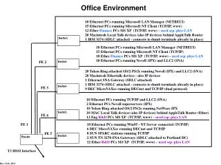
Data Center Design • http://www.spectrum.ieee.org/feb09/7327