Download

1 / 31
310 likes | 327 Vues
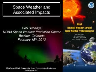
This seminar explores the anomalies caused by radiation effects in space environments, including solar flares, cosmic rays, and radiation belts. It discusses the impact on space agency missions and the design challenges faced by on-board systems. The effects of radiation on different components and the potential hazards in Low Earth Orbit are also addressed. The seminar highlights the need for dependable and high-performing systems in increasingly exposed missions.

E N D
Anomalies associated with radiation effects and the role of space agencies Robert Ecoffet, CNES CERN Seminar, June 10, 2014
Space environment radiation sources Solar flares Cosmic rays Radiation belts Ions Protons Ions Protons Electrons max ~ 300 MeV/n keV- 500 MeV few 1-10 MeV/n keV- 500 MeV eV ~ 10 MeV CERN Seminar, June 10, 2014
Rotation axis Radiationbelts Declination Magnetic dipole axis Geographic equator South-Atlantic anomaly Magnetic equator Polar LEO orbit ~ 400 km Hazard zones in LEO : SAA and poles CERN Seminar, June 10, 2014
Space environment and components • An environment specific to space applications • A major dimensioning constraint for on-board systems • Very fast evolution of electronic technologies • Performance often leads to cutting edge designs • A strong economic drive toward margin reductions • More exposed missions • Smaller satellites (less shielding) Today’s components features Dimensions : 0.1 µm²Time : 1 psCharge : 1 µV More transistors now in a single chip than in whole 1980’s spacecraft designs (GALILEO Jupiter probe for example) CERN Seminar, June 10, 2014
Main radiation effects Single event effects Ionising dose Atomic displacement (e-) p+ p+ p+ e- Ion Trapped charges Oxide + + + + + + + + + + - - + - + - + - - - Oxide Oxide Interstitials • + - + • - + + - • + - - + • + + + Silicon Interface traps Ionisation Silicon Silicon Vacancies Ion 2nd Parametric drift Functionloss Lifetime SET : transient SEU : upset SEL : latch-up SEB : burn-out SEGR : rupture Hot pixels RTS Operating safety Dependability Performances CERN Seminar, June 10, 2014
Single event effects classes Effects in parasitic structures Effects in nominal active structures Exceeding gate oxide breakdown field Turning on parasitic BJT SET : transient Turning on parasitic SCR Analog Transient latch Power MOSFETs CMOS Power MOSFETs SEB SEGR SEU : upset SEL Digital CERN Seminar, June 10, 2014
Space environment vs. CERN > 10 MeV proton yearly proton fluence (outside spacecraft) 50 MeV yearly equivalent fluence (3 mmAl spherical shield) CERN Seminar, June 10, 2014
Yearly doses in sample equipment GEO MEONavigation Outer electron belt Circular Orbits Proton belt and inner electron belt LEO Constellations LEO ObservationConstellations CERN Seminar, June 10, 2014
Spacecraft anomalies • Radiation-induced spacecraft anomalies have been observed since the very beginning of the space era • Single event effects now represent the major part of anomalies (60 to 90%) First satellite failures due to radiation (dose) First reported SEUs (GCR) in satellites First proton latch-up in space Discovery of the radiation belts Nuclear blasts in space First proton SEUs 1957 1962 1963 1975 ~1978 1991 CERN Seminar, June 10, 2014
Classical SEE effects • Memory corruption : single errors to error bursts • Processor crash • Mode swapping • Reset • Switch-off • ADC conversion errors • ADC swapping to autocal. mode • Gain change • Reference voltage change • VCO output frequency change • Transient PLL lock loss • False signals • Star pattern loss • Image corruption • ……. • Equipment loss CERN Seminar, June 10, 2014
Examples of system effects CERN Seminar, June 10, 2014
Cumulated effects (published) Telstar, 1963 Artificial radiation belt Hipparcos- 1993 Apogee motor failed Degraded mission TID degradation of bipolar PROMs and optocouplers Design lifetime was 5 years in GEO Actual lifetime was 5 years in GTO Galileo - 2002 Jupiter radiation belts Many systems affected But outstanding success ! Telstar - 1963 Artificial radiation belts Starfish experiment, 1962 Diode failed in command decoder 7 other satellites failed
SEE : GCR and SPE (published) SOHO (L1) – 2001 GCR : self switch-of, reset, reboot, latch-up SPE : mass memory errors spikes SPOT-1, 2, 3 (800 km, 98°) - 1995 GCR : SEUs in HEF4736 SRAMs TDRS-1 (GEO) – 1991 SEUs in 93L422 bipolar RAMs Possible satellite tumbling GCR ~ 20 events / week Oct. 89 flare : 249 events / 7 days 30% p+, 70% ions MAP (L1) – 2002 5 Nov. 2001, switch to safe-hold condition SET on PM139 from processor reset circuitry 3-7 November 2001 : large solar event Attributed to SPE ion
SEE : trapped protons (published) SAMPEX – 2001 (512 km x 687 km, 81.7°) ERS-1 (780 km, 98°) - 1991 Solid State Recorder upsets MIL-1773 fiber optics bus retries Transients in the photoreceptor Latch-up on CMOS SRAM after 5 daysInstrument lost TOMS / METEOR-3 – 2001 (1183 km x 1205 km, 82.6°) Solid State Recorder upsets ISS, Space Shuttle, LANDSAT, TERRA, AQUA, AURA, HST, GALEX, GLAST, TRMM, ORBVIEW, ENVISAT, ERS-2, METOP, SMOS, CRYOSAT-2, HERSCHEL, INTEGRAL, XMM, SPOT-4, SPOT-5, JASON-1, JASON-2, CALIPSO, COROT, DEMETER, PARASOL, PICARD, Myriade µSATs,
DDD : trapped protons (published – expt *) TOPEX / POSEIDON – 2002 (1336 km, 66°) GLOBALSTAR-1 - 2010 (1441 km, 52°)* 4N49 optocouplers Status circuits Earlier but not mission-critical Thruster command circuits Failures occurred at 8.75 years Design lifetime was 3 years 48 operational satellites and 4 spares. Original constellation deployment in 1998-2000. In the 2002-2004, 24 receivers on 21 satellites affected, 3 satellites failed Radiation design lifetime of individual satellites was 9 years LT RH1014 bipolar devices
STARDUST INTEGRALCHANDRACLUSTER SOHOACEWINDGENESIS GOES-9, 10, 12, 8DMSP-16KODAMAINMARSAT AQUATERRALANDSATTOMS TRMMPOLARFEDSATICESATGALEXMER-1, 2XTERHESSICHIPSATNOAA-17 MIDORI SIRTF SMART-1 MAP MARS ODYSSEY Effects of a major SW event (oct-nov 03) www.sat-index.com
Blurring of VIS camera on NASA / POLAR NASA image CERN Seminar, June 10, 2014
Solar protons “filmed” by SOHO CERN Seminar, June 10, 2014
Solar protons “filmed” by SOHO CERN Seminar, June 10, 2014
Galileo at Jupiter Image of a Sodium volcanic plume on the moon Io contaminated by speckles due to Jupiter radiation belts, JPL image CERN Seminar, June 10, 2014
- T° + + Satellite is a sphere - - + + - Simple geometrical simulations + ON ON - OFF OFF - ? + Sector analysis Radiation activities in project phases Analysis and specification of radiation environment Phase 0 Mission analysis Orbit analysis Environment specification Calculations on simple structures Generic specification of received dose Hardness assurance specification Pre-evaluation of critical components Phase A Feasibility Components are evaluated Evaluation of component radiation performance Interaction structural and system design Risk estimation Phase B Preliminary design Component list analysis Radiation lot verification testing (RVT) Application conditions Radiation levels on actual satellite Local shielding Phase C/D Detailed designQualification Complex structural modelling Functions and application conditions Flight lots testing Lessons learned Anomaly analysis Space weather Phase E Utilisation CERN Seminar, June 10, 2014
Implementation at CNES Mission analysis Mechanical Thermal • “Radiation engineer” function • Singleentry point for radiation issues • Continuityfrom phase 0 to phase E (design to exploitation) • Leads calculations and tests • Interfaces with component procurement engineers (qualification procedures) • Interfaces with designers (functional, electrical, mechanical, thermal,…) • Iterative and concurrent (2-way) process • Interfaces with satellite operators • Similar implementation for satellite prime contractors and main equipment providers Function Electrical Reliability - dependability Operations Radiation engineer Anomalies - failures Dose levels Tests SEE rates CERN Seminar, June 10, 2014
Implementation at CNES • Radiation engineer function • set-up after first SPOT-1 on board computer SEUs (1986) : 50% of these SEUs resulted in 24h mission outage • sad to say, new organizations come often as aftermaths of problems • A long run • I started working on SPOT-5 radiation qualification in 1994 • 20 years after, I’m still recording on-board SEUs ! • How many people ? • 5 radiation engineers for 2406 employees • (ESA : 2254 employees, 4 radiation engineers, 2 technicians) • (Thales Alenia Space and Airbus Satellites : each 15-20 rad. engineers for 6000-7500 staff) • Most of the tests are now subcontracted to test houses (TRAD, ALTER/HIREX…) • Key words : single point, continuity over project lifetime, interaction with designers CERN Seminar, June 10, 2014
CNES, ESA, RADECS CNES 2000 M€ • CNES and ESA • CNES manages the French contribution to ESA • For components and radiation • ESCC, ECSS – space standards • CTB : agencies – industry network • Radiation Working Group • Agencies, primes, providers, test houses, component manufacturers • R&D harmonization • Larger networks • IEEE NSREC • NSREC 2014, Paris (merged with RADECS) • RADECS • University, research, agencies, industry • Conferences, thematic workshops • RADECS 2017 at CERN ! 755 M€ ESA 4000 M€ Member States 2900 M€ E. U. 1100 M€ CERN Seminar, June 10, 2014
Basic Mechanisms of Radiation Effects in Electronic Materials and Devices • Single-Event Charge Collection Phenomena and Mechanisms • Radiation Transport, Energy Deposition and Dosimetry • Ionizing Radiation Effects • Materials and Device Effects • Displacement Damage • Processing-Induced Radiation Effects • Radiation Effects on Electronic and Photonic Devices and Circuits • Single-Event Effects • MOS, Bipolar and Advanced Technologies • Isolation Technologies, such as SOI and SOS • Optoelectronic and Optical Devices and Systems • Methods for Hardened Design and Manufacturing • Modeling of Devices, Circuits and Systems • Particle Detectors and Associated Electronics for High-Energy Accelerators and Nuclear Power Facilities • Cryogenic or High Temperature Effects • Novel Device Structures, such as MEMs and Nanotechnologies • Space, Atmospheric, and Terrestrial Radiation Effects • Characterization and Modeling of Radiation Environments • Space Weather Events and Effects • Spacecraft Charging • Predicting and Verifying Soft Error Rates (SER) • Hardness Assurance Technology and Testing • New Testing Techniques, Guidelines and Hardness Assurance Methodology • Unique Radiation Exposure Facilities or Novel Instrumentation Methods • Dosimetry • New Developments of Interest to the Radiation Effects Community www.nsrec.com
Compared SEU sensitivities 1 Mbit SRAMs - No standard behaviour within a technology “generation”- No scaling factor between generations
A designer’s nightmare The op-amp outputs SET parasitic signals of many volts lasting a few 10 µs The limiter /switch used as a « de-latching » device is itself sensitive to latch-up The comparator changes state on its own Lim The ADC does conversion errors and switches on its own to auto-calibration mode during 1 s. AMP ADC Orange components are latch-up sensitive The DAC outputs voltage swings of many volts COMP DAC The µP does calculation errors, program errors, and crashes The DRAM storage array does row and line bursts of multiple errors The program SRAM does multiple errors µP SRAM The program FlashEPROM exhibits read errors and switches on its own to status mode FlashEPROM DRAM FIFO The FIFO TM buffer memory does addressing conflicts and scrambles write and read pointers