Download
1 / 112
1.13k likes | 1.15k Vues
Explore the mission and upgrades of the NSTX-U upgrade project through key performance parameters, scope, deliverables, and lessons learned.

E N D
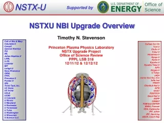
NSTX-U Supported by NSTXU UPGRADE PROJECT CD-4 Review Coll of Wm & Mary Columbia U CompX General Atomics FIU INL Johns Hopkins U LANL LLNL Lodestar MIT Lehigh U Nova Photonics Old Dominion ORNL PPPL Princeton U Purdue U SNL Think Tank, Inc. UC Davis UC Irvine UCLA UCSD U Colorado U Illinois U Maryland U Rochester U Tennessee U Tulsa U Washington U Wisconsin X Science LLC Culham Sci Ctr York U Chubu U Fukui U Hiroshima U Hyogo U Kyoto U Kyushu U Kyushu Tokai U NIFS Niigata U U Tokyo JAEA Inst for Nucl Res, Kiev Ioffe Inst TRINITI Chonbuk Natl U NFRI KAIST POSTECH Seoul Natl U ASIPP CIEMAT FOM Inst DIFFER ENEA, Frascati CEA, Cadarache IPP, Jülich IPP, Garching ASCR, Czech Rep Princeton Plasma Physics Laboratory Office of Science Review LSB B318 September 2nd, 2015 The NSTXU team Neway Atnafu, Bill Blanchard, Jim Chrzanowski, Mark Cropper, Larry Dudek, Charlie Gentile, Stefan Gerhardt, Ron Hatcher, Bob Kaita, George Labik, Steve Langish, Erik Perry, Raki Ramakrishnan, Mark Smith, Paul Sichta, Tim Stevenson, Ron Strykowsky, Mike Williams, Pete Titus, Kelsey Tresemer, et el.
Agenda 8:00 DOE Executive Committee session — Kin Chao 8:30 Welcome — Stewart Prager 8:35 Project Overview, Closeout Doc. and Lessons Learned – Ron Strykowsky 9:50 Transition to Operations – Stefan Gerhardt 10:20 Questions and Discussion 10:35 Break 10:45 Tour 11:15 Breakout Sessions 12:15 Lunch for Committee 1:00 Breakout Sessions 2:45 DOE Executive Session 4:00 Closeout (in NSTXU Control Room Annex) 4:30 Adjourn
Contents • PROJECT OVERVIEW • MISSION • KEY PERFORMANCE PARAMETERS (KPP’S) • SCOPE DELIVERABLES OVERVIEW by WBS • BASELINE DOCUMENTATION • LESSONS LEARNED • CHARGE QUESTIONS
Contents • PROJECT OVERVIEW • MISSION • KEY PERFORMANCE PARAMETERS (KPP’S) • SCOPE DELIVERABLES OVERVIEW by WBS • BASELINE DOCUMENTATION • LESSONS LEARNED • CHARGE QUESTIONS
Princeton Plasma Physics Laboratory-NSTXU Field Coil Power Conversion Bldg Motor Generators RF Transmission lines Magnet Power Rectifiers Neutral Beam Power Conversion Bldg 138kV electric transmission line to PPPL NSTXU Test Cell Centerstack Fabrication area Mockup Bldg D-Site Tunnel from NSTXU control room to D-Site C-Site RF Bldg NSTXU Control Room (basement level) You are here
NSTXU Device • The NSTX device is exploring a novel structure for the magnetic field used to contain the hot ionized gas, called “plasma”, needed to tap this source of fusion energy. • Mission of the NSTX is to establish the potential of the ST configuration as a means of achieving practical fusion energy. • Not a steady state machine. Pulse length < 6 sec. • Design rep rate <40 minute • History: • Original project completed 1999 • First beamline added 2000. • Upgrade project CD-0 mission need Feb 2009 • CD-1 Apr 2010 • CD-2 Dec 2010 • CD-3 Dec 2011
NSTXU – Current Completed Configuration Neutral Beam (NB) #1 NB #2 duct in place. Existing RF pipes New Centerstack Neutral Beam (NB) #2 High Voltage Enclosures (HVE) Neutral Beam Duct/TVPS New Platforms
Major Machine Components Description Outer TF coils New NB port PF Coils
Centerstack Components Umbrella Structure TF Flex Bus and Support Structure Centerstack Assembly Outer TF Coils
Centerstack Components TF cooling hose connections TF flex connector Outer TF lead extensions OH Coil (4 layers wound onto TF conductors) Ceramic break & mounting flange to vacuum vessel PF 1 A,B, &C coils Inner TF conductor (36) Casing Plasma Facing Components (PFC’s)
Second Neutral Beam NBL2 Duct w/ new TIV Torus Vessel Pump System Duct Port Extension Bay J-K Cap (Required NSTX Vessel Modification) NBI Armor addition
Contents • PROJECT OVERVIEW • MISSION • KEY PERFORMANCE PARAMETERS (KPP’S) • SCOPE DELIVERABLES OVERVIEW by WBS • BASELINE DOCUMENTATION • LESSONS LEARNED • CHARGE QUESTIONS
Technical Performance Baseline Parameters (defined in section 2.2.1 of the Project Execution Plan (PEP)) • Design Parameters • Toroidal field from 0.5 tesla to 1.0 tesla; • Pulse length from ~1.0 second to 5.0 seconds; • Plasma current from 1MA to 2MA; • Neutral beam heating from 5-7MW to 10-14MW • Hardware components designed and tested to these levels • Achievement of Design parameters to be phased in over 3 years) • (ref readiness for operations talk)
NSTX Upgrade Deliverables • Double field and current Center Stack (CS) Upgrade. • Design, build and install new CS assembly including; • new toroidal field (TF) hub assembly, • new TF flag assemblies, • new ceramic break, • new inner TF bundle, • new ohmic heating coil, • new plasma facing component (PFC) tiles, • new poloidal field (PF) 1a, b & c coils • Analyze and upgrade components supports • Power, controls, water, services • Coil protection system This represented a major modification to an existing fusion device
NSTX Upgrade Deliverables 2) Double neutral beam power & more tangential injection 2nd Neutral Beam-line (NBL). • Decontaminate and prepare a TFTR neutral beam-line (NBL) for installation on NSTX. • Evaluate and refurbish internal components as necessary (cryogenic panels, beam dumps, bending magnets, beam scrapers, calorimeter, etc.). • Relocate the NBL and • Provide a second set of beam-line services (e.g., power, water, vacuum, cryogenics, etc.).
Contents • PROJECT OVERVIEW • MISSION • KEY PERFORMANCE PARAMETERS (KPP’S) • SCOPE DELIVERABLES OVERVIEW by WBS • BASELINE DOCUMENTATION • LESSONS LEARNED • CHARGE QUESTIONS
CD-4 milestone completion criteria Defined in section 2.2.2 of the Project Execution Plan (PEP) 2.2.2.2 Demonstrated Performance The major milestone marking the transition from a fabrication project to an operating facility is the first plasma milestone (CD-4). First plasma is defined as an ohmically heated discharge > 50 kA at a toroidal magnetic field of > 1 kG. The operations phase will resume upon completion of the first plasma milestone. The installation of the second neutral beam on NSTX shall be considered complete at the stage where each item below has been demonstrated: Beamline water, vacuum, cryogenics, and feedstock gas services have been attached to the beamline; A Torus Isolation Valve and duct interconnects the NSTX vacuum vessel and the neutral beamline; Local Control Centers have been powered on to monitor power supply status, and; Project will be verified as complete when a 40,000 electron-volt beam has been produced and injected into the armor for >.050 seconds
KPP #1 - >50kA plasma Status: Achieved 8/10/2015. KPP GoalAchieved OH Discharge >50kA >100kA TF Magnetic Field >1kG 5kg Plasma current (left) and toroidal field data (right) for ~100kA, BT = 0.5T plasma in NSTX-U for CD-4 KPP (note: 0.5T = 5kG).
KPP #1 - >50kA plasma Camera image (left) and EFIT reconstruction (right) for NSTX-U CD-4 KPP plasma
KPP #2 - >40kV Beam Injection into Armor Status: Achieved 5/11/2015. Five 45KV @ 12 amps shoots into the armor for >50ms. • Photo of control screen showing status of NB2; • TIV open • Calorimeter out • Ready to inject
KPP #2 - >40kV Beam Injection into Armor (continued) Power and duration of shot 100 msec (5 x 20 msec per grid) 45 kV (1.5 grid division x 200mV/div x 150 kV/volt)
KPP #2 - >40kV Beam Injection into Armor(continued) Location of beam – as designed Actual Plan • BL 2 • BL 1 • A • B • C • B • C
Contents • PROJECT OVERVIEW • MISSION • KEY PERFORMANCE PARAMETERS (KPP’S) • SCOPE DELIVERABLES OVERVIEW by WBS • BASELINE DOCUMENTATION • LESSONS LEARNED • CHARGE QUESTIONS
Project Scope WBS Breakdown • WBS Dictionary per the PEP in Appendix A of the closeout report. (What we promised) • Scope highlights by WBS starting on slide 22.
Project Scope WBS Breakdown (continued) • Technical Performance Achieved – Project Closeout Acknowledgement forms in Appendix B of the closeout report (What we delivered)
Extensive analysis required for magnet supports and vacuum Vessel WBS 1.1 CA 1000 Pete Titus Reinforcement of the TF outer leg support structure
WBS 1.1 CA 1000 Pete Titus Analysis & Value Engineering – An Iterative process 96 Plasma Equilibria (Physics) Design Point SS (Magnetic loads) Analysis (ANSYS, Workbench) Design (CAD Models) Field Assembly (Field Experience) • TF Inner Leg and Flex Joint Qualification • Concept, Initial Analysis • TF Inner Joint Stress, Contact Pressures • TF Current Diffusion • TF Torsional Shear • TF Stress, Insulation Tension Stress • TF Tooth Interface w/Umbrella Structure • Vessel and Umbrella Structure • Original, Early Upgrade • Full 360 degree Model from Pro E, Reinforcements • TF Loading on Alum Blocks, hang, • Vessel Lid and Bottom Cover Connection, Central Column to Umbrella • Vacuum loading with neutral beam ports • Pushing the structural limits of the existing machine required significant analytical modeling in concert with Physics, engineering and field input to optimize the design. • Over 28,000 hours of analysis • Outer TF Leg Analysis • Torsional OOP Loads • Stress, Insulation Tension Stress • Outer Leg Support Other • Center Stack • Plasma Facing Components • Inner PF Supports • Outer PF Supports • Lower Support Pedestal • HHFW Antenna Analyses Disruption • OPERA Axisymmetric • Vessel and Passive Plates, Early Upgraded Loads +DLF • Detailed Vessel and Passive Plates • EMAG Transient Dynamic Analysis • Center Stack Casing with Halo Currents
PFC’s WBS 1.1 CA 1001 Kelsey Tresemer CA 1002 Neway Atnafu New PCHERS Passive Plate (not installed) NSTXU CALC 12-01-01 PP and Vessel Disruption (Titus et.al. /Zhai) NSTXU CALC 12-03-00 OPERA 2D Disruption (Hatcher/Titus) CS Casing and Bellows Assy NSTXU CALC 133-05-00 CS Casing Halo(Brooks/Titus) NSTXU CALC 132-11-00 CS Casing Stresses(Titus/ Unassigned) NSTXU-CALC-133-03-00 Center Stack Casing Disruption Inductive and Halo Current Loads P.Titus Myatt,Brooks NS TXU-CALC-133-1 0-00 Center Stack Casing Bellows Peter Rogoff I.Zatz PFC Tiles Installed NSTXU CALC 11-03-00 Tiles Brooks NSTXU CALC 11-02-00 General Tile(Boales/ Brooks) NSTXU CALC 11-01-00 PFC First Wall Heat Balance (Brooks/Zhang) Additional work scope for CHI gap tile design NSTXU CALC 40-01-00 Diagnostics Review(Boales/Zhai) New Passive Plate supports and sensors NSTX-U Monday,December8,14
Coil Supports WBS 1.1 CA 1200 Mark Smith
UmbrellaLidReinforcements WBS 1.1 CA 1200 Mark Smith Upper Lid Umbrella Replacement Leg and sliding foot
Outer TFReinforcement WBS 1.1 CA 1200 Mark Smith NSTXU-CALC-132-11-00- Ring Bolted Joint - (Rogoff, Zatz) NSTXU-CALC-132-04-00 Analysis of TF Outer Leg (Zhang,Titus) TFOLConnectingRodAssembly TFOLClampHoldDown TFOLSupportLinkAssembly TFOLSupportRing
TheNewCenterstack WBS 1.1 CA 13xx Jim Chrzanowski & Steve Raftopoulos • Design, Build and Install New CS Assembly including : • New TF Hub Assembly • New TF Stub and Flex Assemblies • New Inner TF Bundle • New Ohmic Heating Coil • New Inconel Casing & Insulation • New PFC Tiles • New Poloidal Field 1a, b & c Coils • New Ceramic Break • R&D Activities to support above work • TF electrical joint testing • OH braze joint testing • Friction Stir Welding Tests
TFBundle,OHandExtensions WBS 1.1 CA 13xx Jim Chrzanowski & Steve Raftopoulos TFFlexJointsFabrication NSTXUCALC132-06-00TFFlexJoint (Willard) TFLeadExtensions TFLeadFingerSupports NSTXU-CALC-132-14-00TFStrap AssemblyFingers OHPreloadAssembly NSTXUCALC133-04-00OHPreload Bellevilles(Rogoff/Zatz) TF Bundle and Conductors 1.1.0 NSTXU-CALC-132-03-00 Torque Egns for Design Point (Woolley/ Titus) NSTXU CALC 132-10-00 TF Cooldown FCOOL (Zolfaghari/Kalish) NSTXU CALC 132-05-00 TF Coupled EM- Thermal (Zhang) NSTXU-CALC-132-08-00 Determination of shear Forces Between the TF conductors and Insulation and the G-10 Insulating Crown.A. Zolfaghari T.Willard NSTXU-CALC-132-07-00 Maximum Torsional Shear Stress P.Titus R.Woolley OH Coil Assembly Thermal Stresses on OH-TF Coils NSTXU-CALC-133-02-00 NSTXU-CALC-133-06-00 OH Coolant Hole Optimization A. Zolfaghari NSTXU-CALC-133-08-00 OH Stress Analyses A. Zolfaghari NSTXU-CALC-133-09-00 OH Fatigue and Fracture Mechanics P.Titus I.Zatz NSTXU-CALC-133-11-00 OH & PF1 Electromagnectic Stability Analysis P. H.M.Fan Titus / Zolfaghari CSCasing NSTXUCALC133-05-00CS CasingHalo(Brooks/Titus) NSTXUCALC133-07-00OHCoax (Mardenfeld) NSTXUCALC132-08-00TF CollarPin/Shear (Zolfaghari) NSTX-U Monday,December8,14
PF1Coils WBS 1.1 CA 13xx Jim Chrzanowski & Steve Raftopoulos PF1C Upper and Lower NSTXU-CALC-133-11-00 OH & PF1 Electromagnetic Stability Analysis NSTXU-CALC-133-01-01 Structural Analysis of the PF1 Coils, leads and Supports, Rev 1 NSTXU-CALC-133-15-0 Analysis of the PF1C mandrel/Case CHI Gap thermal response including thermal shield design PF1B Upper and Lower NSTXU-CALC-133-11-00 OH & PF1 Electromagnetic Stability Analysis NSTXU-CALC-133-01-01 Structural Analysis of the PF1 Coils, leads and Supports PF1A Upper and Lower NSTXU-CALC-133-11-00 OH & PF1 Electromagnetic Stability Analysis P. NSTXU-CALC-133-01-01 Structural Analysis of the PF1 Coils, leads and Supports
WBS 1.1 CA 13xx Jim Chrzanowski & Steve Raftopoulos • Assembly of centerstack Fabrication of center stack performed by PPPL with components supplied by industry Assembly four quadrants of conductors Assembling first of 4 quadrants of conductors Final VPI of OH/TF bundle Winding of OH conductor around TF bundle Total of 6 risky VPI (Vacuum Pressure Impregnation) performed. All very successful.
OHAquapourRemoval WBS 1.1 CA 13xx Jim Chrzanowski & Steve Raftopoulos 100millAquapour gap TF Coil OH Coil • During VPI, epoxy saturated the Aquapour turning it into waster resistant substance. • • No solution for removing the remaining Aquapour- epoxy mixed material. Decision to leave Aquapour in place. • Independent peer review conducted to determine mitigation plan. • Mitigated via DCPS and Operation procedures.
OH/TF center stack bundle WBS 1.1 CA 13xx Jim Chrzanowski & Steve Raftopoulos Final sanding and clear coat applied. Outer ground plane applied.
WBS 1.1 CA 13xx Jim Chrzanowski & Steve Raftopoulos, Kelsey Tresemer • Plasma Facing Components on CS casing PFC tiles installed PFC tiles being installed on the CS Casing
WBS 1.1 CA 13xx Jim Chrzanowski & Steve Raftopoulos WBS 1.1 CA 13xx Jim Chrzanowski & Steve Raftopoulos CS casing over the OH/TF bundle
Second Neutral Beam Scope WBS 1.2 Tim Stevenson A TFTR Neutral Beamline was Decontaminated and relocated to the NSTX Test Cell NSTX test cell TFTR test cell
WBS 1.2 CA 2430 Tim Stevenson NSTXNBIU- Beamline Decontamination • Decon Goals and Approach • Goals - tear it down, clean it, evaluate BL & components prepare for refurbishment minimize dose (zero is good.) minimize rad waste reduce levels as low as reasonably achievable minimize BL2 impact on NSTX Operations • Approach - hands on work boots, PC suits, gloves, hoods rags, swiffer poles, sprayers H2O2, Windex, swiffer pads, DI water • Repeated comprehensive HP surveys to control areas and assess progress extensive support by ERWM to provide supplies and manage radwaste
Beamline and Lid Relocation WBS 1.2 CA 2425 Mark Cropper /Tim Stevenson BL2BoxLift BL2LidLift
Second Neutral Beam Relocated WBS 1.2 CA 2425 Mark Cropper/ Tim Stevenson • Beam box = 40 tons • Lid = 14 tons • Began work February 2009 • 30,000 hours (>17 person years) for decontamination, refurbishment, relocation design
WBS 1.2 CA 2425 Tim Stevenson NBI BL Alignment • Install supports • Fabricate shims • Install spiders • Install jacking systems • Setup optical alignment • Survey height from BL1 and VV • Install shims • Survey trajectory from metrology • Set and reset BL • Confirm alignment • Verify alignment • Set machine targets • Set wall onument references • Adjust CL Height to 13’ midplane of machine • Adjust to tangency radii 110,120,130 cm (Yaw) • Adjust Pitch Level • Adjust Roll – Level • Establish referencesfor platform, 90 inch flange,source rails • Completed safely on a contaminated BL with stack ventilation
WBS 1.2 CA 2440 Mark Cropper BL2Sourcerelocationcompletedx3
WBS 1.2 CA 2425 Tim Stevenson N4ABC High Voltage Enclosure (3) relocation
WBS 1.2 CA 2425 Tim Stevenson N4ABCHighVoltageEnclosurerelocations
WBS 1.2 CA 2425, 2450 Tim Stevenson/Mark Cropper BL2TransmissionLinerelocationx3 • HVE reassembly and reconnections completed • HVE telemetry installed, tested, operational • HVEs filled with SF6 • Transmission Lines rebuilt, installed, plumbed for SF6 overpressure recapture • Platforms modified and installed
NSTXNBPowerCablesinTCB,toNTC WBS 1.2 CA 2470/2475 Raki Ramakrishnan/ Mark Cropper Cableandtraypath Cryo lineinstallation path