Download
1 / 28
420 likes | 832 Vues
Particle Measuring Technique Co.,Ltd. CERTIFIED CLEANROOM. Clean Room Certified by…. NEBB ( National Environmental Balancing Bureau ). Standard Clean Room. Federal Standard 209E ( FS – 209E ) ISO Standard ( ISO 14644 – 1 ) Good Manufacturing Practice ( GMP ). Class.

E N D
Particle Measuring Technique Co.,Ltd. CERTIFIED CLEANROOM
Clean Room Certified by… NEBB (National Environmental Balancing Bureau)
Standard Clean Room • Federal Standard 209E ( FS – 209E ) • ISO Standard ( ISO 14644 – 1 ) • Good Manufacturing Practice (GMP)
Class Count/ ft3 0.1μm 0.2μm 0.3 μm 0.5 μm 5.0 μm 1 35 7.5 3 1 10 350 75 30 10 100 750 300 100 1000 1000 7 10000 10000 70 100000 100000 700 Federal Standard 209E (FS-209E)
Class Count / m3 0.1 μm 0.2μm 0.3μm 0.5µm 1.0µm 5.0µm ISO 1 10 2 ISO 2 100 24 10 4 ISO 3 1000 237 102 35 8 ISO 4 10000 2370 1020 352 83 ISO 5 100000 23700 10200 3520 832 29 ISO 6 1000000 237000 102000 35200 8320 293 ISO 7 352000 83200 2930 ISO 8 3520000 832000 29300 ISO 9 35200000 8320000 293000 ISO Standard ( ISO 14644 – 1 )
Grade Count/ m3 At rest In operation 0.5µm 5.0µm 0.5µm 5.0µm A 3520 20 3520 20 B 3520 29 352000 2900 C 352000 2900 3520000 29000 D 3520000 29000 Not defined Not defined Good Manufacturing Practice (GMP)
Test Description • Airborne Particle Count Test • Airflow Velocity Test Under • Temperature Test • Relative Humidity Test • Room Pressurization Test • Scan Leak Test Hepa • Scan Leak Test PAO • Light Intensity Level Test • Sound Pressure Level Test
Type of Condition • AS BUILT • The condition where the installation is complete with all services connected and functioning but with no production equipment, materials, or personnel present • AT REST • The condition where the installation is complete with equipment installed and operating in a manner agreed between the customer and supplier, but with no personnel present • OPERATIONAL • The condition where the installation is functioning in the specified manner, with the specified number of personnel present and working in the manner agreed upon
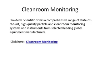
Procedure ForAirborne Particle Count • Purpose • To measure the airborne particulate level in the Cleanroom and to determine the room Cleanliness • Classification as per Federal Standard 209E. • Instrumentation and Equipment • PMS Lasair II / 310A counter • Specification • Test Condition: At Rest / As Built / Operational • Allowable Count Limit for each particle size • Class 1,000 : <1,000 count/ft3 @ 0.5μm & greater • : <7 count/ft3 @ 5.0μm & greater • Class 100 : <300 count/ft3 @ 0.3μm & greater • : <100 count/ft3 @ 0.5μm & greater • Procedure • Reference: Federal Standard 209E • NEBB Procedural Standard for Certified Testing Of Cleanroom • This test was conducted after all the other tests had been completed. • The Cleanrooms were purged for at least 12 hours before testing commences. • The Cleanrooms were divided into test grids according to their Cleanliness Class as per Federal Standard 209E as follow: - • Class 1,000Grid size not exceeding 31.6 sq ft3. • Class 100Grid size not exceeding 25 sq ft3. • The sample time was set to 1 min per sample with the counters’ sample rate at 1 ft3/min. • A minimum of 1 sample was taken at the center of each grid, at a height of 1 meter above the floor. When the count was greater than 75% of the allowable count limit, 3 samples was taken at that sample location. • When an obstruction was encountered, the sample was taken at 12” above the obstruction. • The average, standard deviation and 95% upper confidence limit were computed from the collected data.
Procedure For Temperature & Relative Humidity Test • Purpose • To determine the capability of the Cleanroom air handling system to maintain the air temperature and relative humidity • within specified limits. • Instrumentation and Equipment • TSI Thermal Hygrometer: 8722-M-GB • Specification • Average Temperature : 20 ~ 24oC • Average Relative Humidity : 40 ~ 70 % • Procedure • All airflow balancing was completed prior to this test. • The air conditioning system was operated continuously for at least 24 hours prior to the commencement of the test. • The Cleanrooms were divided into test grids of no larger than 100 ft2 • The temperature & RH meter was held at the center of the test grid at 1 meter above the floor. • When an obstruction was encountered, the measurement was taken at 6” above the obstruction. • The readings for all the other grids were taken and recorded. • The average temperature and relative humidity of the Cleanroom were computed from these data.
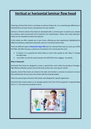
Procedure ForAirflow Velocity Test • Purpose • To determine the airflow velocity of the filters installed in the Cleanrooms. • Instrumentation And Equipment • Airdata Electronics Micromanometer, ADM-870 • Specification • Test Condition: At Rest / As Built / Operational • Two (2) velocity values are to be taken for each 2’x4’ HEPA filter at 75 mm. from the filter surface • Average : 0.41 - 0.61 m/s • Two (2) velocity values are to be taken for each 2’x4’ HEPA filter at 150 mm. from the filter surface. (Under Laminar Flow Hood) • Average: 0.36-0.56 m/s • Procedure • Reference: IES Recommended Practice, IES-RP-CC006.2 Testing Cleanrooms • NEBB Procedural Standard for Certified Testing of Cleanroom • Every filter was divided into 2 test grids each. • The electronics micromanometer was setup with the Velgrid attachment and the temperature probe for automatic compensation of air density variation. • The Velgrid, having a dimension of 14” x 14”, was placed at the center of the grid, with the Velgrid’s standoff spacers just touching the outlet filter surface. The Velgrid’s sides are to maintain parallel to the filter edges. • One reading was taken and recorded for each grid.
Procedure ForRoom Pressurization Test • Purpose • To determine the capability of the Cleanroom system to maintain the specified pressure differential. • Instrumentation and Equipment • Electronic Micromanometer: ADM-870 • Specification • Test Condition: At Rest / As Built / Operational • Differential Pressure: 0.05”WG wrt adjacent / less stringent room • Procedure • All airflow balancing were completed prior to this test. • All doors into the Cleanroom and the reference areas were closed throughout the duration of the test. • The differential pressure between the Cleanroom and the adjacent room was measured and recorded with Electronic Micromanometer.
Procedure ForHEPA Filter Installation Leak Test Purpose : To verify the absence of bypass leakage (between filter frame and ceiling grid system) in the installation of the filters and confirm that the installed filters are free of defects and small leaks. Instrumentation and Equipment PMS Lasair II / 310A counter Airdata Electronics Micromanometer, AMD-870 Specification • Test Condition: At Rest / As Built / Operational Note: • No additional aerosol challenge will be introduced to the upstream of the filters being tested. • Not More than 1 particle at size 0.3 micron and greater must be detected in the downstream of the filter systems • For each filter, any repair surface must not constitute more than 0.5 sq.inch. Procedure Reference : IEST Recommended Practice, IEST-RP-CC001.3 HEPA and ULPA Filters IEST Recommended Practice, IEST-RP-CC006.3 Testing Cleanrooms NEBB Procedural Standard for Certified Testing Of Cleanroom • The filter’s face velocities were determined to ensure that they were within the general design range. • The upstream concentration was taken at 0.3 micron and greater. This was taken for information only. • Laser Particle Counter with a resolution of 0.3 micron was use for the leak test. The sampling flow rate of the counter was 1 ft3/min. • Rectangular particle counter probe was use to scan the filters. The probe dimension was selected to achieve iso-kinetic sampling. The scanning rate used was in accordance to the above reference. • The probe was held at 1” from the frame at filter surface during scanning. A count of 1 or more will force a sustained residence time of the probe at the location to assess the source of the detected counts. • All confirmed or suspected leaks were identified and recorded. Re-test were conducted after remedial action had been taken When filter are beyond repair and replacement was made, record was made to reflect the replacement.
Procedure ForHEPA Filter Installation Leak Test(Photo meter Method) • Purpose • To insure and confirm that the HEPA filter system is properly installed by verifying the absence of bypass leakage • in the installation and the installed filters are free of defects and pinhole leaks. • Instrumentation and Equipment • ATI Aerosol Photometer ,Model 2H • Specification • Test Condition: At Rest / As Built / Operational • 1 Upstream Concentration: • Minimum value 20 µm/litre • Preferred Range 10 - 100 µm/litre • 2 Maximum allowable penetration < 0.01 % of upstream
Procedure ForHEPA Filter Installation Leak Test(Photo meter Method) Procedure Reference : NEBB Procedural Standard for Certified Testing Of Cleanroom ,2nd Ed IEST Recommended Practice, IEST-RP-CC006.3 Testing Cleanrooms. 1. The filters face velocities are first determined to ensure that they are within the general design range. 2. The photometer and the aerosol generator are then set-up according to the manufacturer’s instruction. 3. Emery 3004 aerosol is then generated with the generator and introduce at the upstream of the filter (s). 4. Upstream concentration ,in µm / liter, is then measured. The sampling point should immediately (subject to physical site constraint) ahead of the filter under tests. Appropriate adjustment, if necessary , is made to ensure that the concentration is within the preferred range. 5. Once upstream concentration is satisfied and set, the photometer will be setup for downstream penetration measurement. 6. Rectangular sampling probe will be used to scan the filters. The probe will be held at approximately 1”from the frame and filter surface during scanning. The maximum concentration level will be recorded. 7. Upon completion of the tests, the upstream challenge concentration is sampled again to ensure consistency of the challenge throughout the test. 8. Certificate Of Compliance will be issued for each HEPA filter / filter bank that meet the required specification . A sample of the certificate is attached.
Procedure For Light Intensity Level Test • Purpose • To determine the light intensity level at working height level within the Cleanrooms. • Instrumentation and Equipment • Digital Lux Meter: LX-50 • Specification • Test Condition: At Rest / As Built / Operational • Average Light Intensity Level : 700 Lux ~ 880 Lux • Procedure • All fluorescent lighting were operated for at least 100 hours to ensure ‘proper seasoning.’ • The lighting ware operated continuously for least 2 hours to allow for temperature stabilization prior to the actual commencement of the test. • The Cleanrooms were divided into test grids of no larger than 100 ft2. • One reading was taken at the centre of each grid and at a height of 1 meter above the floor. • When an obstruction was encountered, the measurement was taken at 6” above the obstruction. • The readings for all the other grids were taken and recorded. • The average light intensity level of the Cleanroom were computed from these data.
Procedure For Sound Pressure Level Test • Purpose • To measure the airborne sound pressure level within the Cleanroom produced by the basic Cleanroom • mechanical and electrical systems. • Instrumentation and Equipment • Sound Level Meter , Cesva SC-2c • Specification • Test Condition: At Rest / As Built / Operational Average Sound Pressure Level : 70 dBA. • Procedure • All airflow balancing was successfully completed prior to this test. • All fan filter modules and air conditioning equipment were switched on before any readings were taken. • The Cleanrooms were divided into test grids of no larger than 10’x10’ • The sound pressure level meter was placed 1 metre above the floor and with the sensor pointing in the • direction of the operating module. • The sound pressure level , in dBA, was taken for each location. • When an obstruction was encountered, the measurement was taken at 6” above the obstruction, provided it • was still within the entrance plane. • The average sound pressure level of the Cleanroom was computed form there data.
Reference Customer • Leader Industrial • NMB • Compart • ISCM • Belton • Nidec • Casio • Johnson & Johnson • WD • Epson Toyocom • Seksun Technology • Olic • Kawasumi • Urgo • Better Pharma • Bangkok Hospital • Siriraj Hospital • Childen Hospital • NSTDA • GHP • Chulabhorn Research Institute
Reference Customer • Seagate • Bumrungrad Hospital • CP Meji • MEGA Life • Central Lab • Sema Technology • M & H • Min Aik • Seiko • Khonkaen Hospital • NOK • JCY • NHK • Metal Form • AGC • E & Tech • PSC • Solar Lens • Hoya • Transition • MTEC • Chulalongkorn University
THANK YOU Contact Us At : Tel : 02-536-5316-8, 02-536-5376-8 Fax : 02-536-5354 sales@pmt.co.th www.pmt.co.th