
Adjustment :
1/2. Adhesive Pad Demonstrator Stanford University – BDML July 2010. 1. Ben Kallman & Julia Lee Email: bkallman @stanford.edu. Assembly:

Adjustment :
E N D
Presentation Transcript
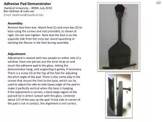
1/2 Adhesive Pad Demonstrator Stanford University – BDML July 2010 1 Ben Kallman & Julia Lee Email: bkallman@stanford.edu Assembly: Remove foot from box. Attach foot (1) and cross bar (2) to base using the screws and nuts provided, as shown at right. Do not over tighten. Note that the foot is on the opposite side from the cross bar. Avoid squashing or twisting the flexure in the foot during assembly. Adjustment: Adjustment is easiest with two people on either side of a window. Have one person put the wrist strap on and touch the adhesive pad to the glass, letting the demonstrator hang, and supporting it gently, if necessary. There is a screw (3) at the top of the foot for adjusting the pitch angle of the pad. There is also some play in the screws that mount the foot to the base, which can be used to adjust the side-to-side (yaw) angle of the pad to make it perfectly vertical when the base is hanging. If the adjustment is correct, a fairly large region of the pad will be in direct contact with the glass, centered about 2/3 of the way up the pad. If one side or corner of the pad is not in contact, the alignment is not correct. 2 3
2/2 Use: Once adjusted, the device should easily attach when brought into contact with a smooth surface and allowed to hang. To release, just lift the weight. Always use the wrist strapwhen demonstrating the device, as the weight is more than enough to break the device if it falls. If the adhesive pad becomes dirty, you can clean it by gently pressing a sticky tape against the surface. To test compliance, let hang on wall and try pushing on either side of the crossbar. Ankle and adhesive should allow for a few degrees of rotation. Attaching your own adhesives: To test your own adhesive pads, loosen the two small screws that clamp the carbon fiber strips in place (see figure at right) just enough to slide out the strips. To create your own pad, attach your adhesive material to the 1’’x1.5’’ acrylic rectangle (or any other material of choice) and glue this piece to the carbon fiber strips. Slide the strips back under the plastic piece and tighten the screws. Do not over tighten. About the device: This demonstrator mimics the behavior of the ankle and foot suspensions in the StickybotIII* robot at Stanford. The weight is equal to ½ the total robot weight. The idea is that any adhesive that works well with this demonstrator should also work well with the robot. Ideally, attachment and detachment should require very little effort. The demonstrator comes equipped with an “h4” hierarchical adhesive pad, which is easier to align than some of the previous adhesives, but produces less normal adhesion, particularly on surfaces that are not completely smooth. Loosen screws just enough to remove carbon fiber strips *http://bdml.stanford.edu/twiki/bin/view/Rise/StickyBotIII