Download
1 / 42
420 likes | 550 Vues
This report outlines the status of the US Dual Coolant Lithium Lead (DCLL) Test Blanket System (TBS) as of August 2, 2010. It includes a comprehensive overview of requested information regarding testing programs, operational objectives, safety assessments, hazard identification, and decommissioning procedures. The report, issued by the Idaho National Laboratory, details the design features, components classification, safety principles, and expected maintenance activities necessary for ensuring the safe operation of the DCLL TBS within the ITER framework.

E N D
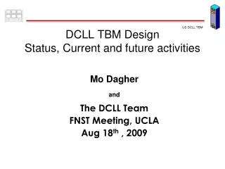
US DCLL TBS Preliminary Safety Report Status Brad Merrill & Lee Cadwallader, INL Clement Wong, GA Mohamad Dagher, Mahmoud Youssef & Alice Ying, UCLA For the U.S. DCLL TBM Team Port cell DCLL TBM FNST/PFC/MASCO Meetings August 2nd, 2010 – UCLA
Status of US DCLL TBS PrSR (1/6) • A copy of the US DCLL Test Blanket System (TBS) Preliminary Safety Report (PrSR) was transmitted to the ITER IO (L. Giancarli) on 7/1/2010 • Issued as an Idaho National Laboratory Report (INL/EXT-10-18169) • Report is more than 120 pages. Our DDD was only 208 pages. • Requested information: • DCLL-TBS TESTING PROGRAM IN ITER • Main features of the DCLL-TBS • Test Program objectives • Test Program schedule • TEST BLANKET SYSTEM DESCRIPTION • Principles of TBS operation • Irradiation and loading conditions • Functional Objectives • Operational Objectives • GENERAL DESCRIPTION • Summary of DCLL TBS design • Equipment layout • Design description of main systems and corresponding components location including: DCLL TBM-Set, Cooling Circuit (s), Coolant Purification Circuit (s), Tritium Extraction Circuit (s), Control System • Description of materials (including all impurities)
Status of US DCLL TBS PrSR (2/6) • Requested information (cont.): • ACTIVATION AND HAZARDOUS INVENTORIES • Radioactive Inventory and Decay Heat • Dose rate from these inventories • Biological Potential Hazards for inhalation and ingestion • Major troublesome radioisotope • TBS COMPONENT CLASSIFICATIONS • List of all TBS components • Safety Important Component classification • Pressure Equipment Directive (PED)/Equipment Safety Pressure Nuclear (ESPN) classification • Quality classification • Seismic classification • GENERAL OPERATIONAL STATES AND CONTROL PRINCIPLES IN THE VARIOUS ITER OPERATIONAL STATES • DCLL TBM-Set components • Cooling Circuit (s) • Coolant Purification Circuit • Tritium Extraction Circuit (s) • Control System 3
Status of US DCLL TBS PrSR (3/6) • Requested information (cont.): • Description of the expected maintenance activities (including equipment & personnel access requirements) • TBM Frame Assembly • Pipe Forest assembly • Port Cell Auxiliary Equipment unit (AEU). • Helium Coolant equipment in the Tokamak Cooling Water System (TCWS) vault annex (VA) • GENERAL SAFETY PRINCIPLES AND DESIGN FEATURES • Safety design principles and Requirements • Defense-in-depth • ALARA • Safety design features and TBS safety functions • Fusion Power Termination System signals • Minimization of radioactive inventory • Confinement systems • Passive heat removal and other structural integrity features 4
Status of US DCLL TBS PrSR (4/6) • Requested information (cont.): • DESCRIPTION OF POTENTIAL HAZARDS and ADOPTED SAFETY MEASURES • Direct Radiation Fields • Tritium • Activated Products • Cryogenic liquids • Potential chemical reactions • Hydrogen Deflagrations/Detonations • Fire • Other potential source terms • GENERAL SAFETY OBJECTIVES AND RELEASE GUIDELINES • ITER zoning for Radiation, Ventilation, Beryllium, Fire, and Magnetic Field and TBS compliance with them • General safety objectives (Dose Limits) • Estimated releases 5
Status of US DCLL TBS PrSR (5/6) • Requested information (cont.): • SAFETY ASSESSMENT • Normal operation • Gaseous and liquid releases during operations • Gaseous and liquid releases during maintenance • Design Basis Accidents • Identification of reference accidents Design Basis Accidents (DBAs) • Consequence analysis of DBAs inside: ITER Vacuum Vessel, Port Inter-space, Port Cell, Helium Cooling System Room, Tritium Building, and Inside Hot Cell • Beyond Design Basis Accidents • Occupational Radiation Exposure (ORE) during normal maintenance • Equipment inside port cell • Maintenance inside Cooling System Room • Maintenance inside Tritium System Room • TBM-set maintenance inside hot cell • AEU maintenance inside hot cell • Radiation exposure during TBM replacement 6
Status of US DCLL TBS PrSR (6/6) • Requested information (cont.): • DECOMMISSIONING AND WASTE • Identification of waste mass, volume, specific activity, decay heat, tritium levels and tritium degassing rate. Categorize waste according to French and ITER waste burial classifications • To date two reviews have been completed without significant findings • The US was the only ITER Partner to meet the June 2010 deadline for PrSR submittal 7
TBS component list • A preliminary list of DCLL TBS components appears in Table 3.6.1-1 of the DCLL TBS PrSR. Table 3.6.1-1. Listing of US DCLL TBS components • TBS system name • PbLi • Primary helium • Secondary helium Quantity Component identifier
TBS component Classification (1/4) • DCLL TBS component PED/ESPN classification • PED classification - pressure hazard category 0, I, II, II, and IV taken from Figure 2 of ITER_D_2F3WWR_v1_3 • ESPN nnuclear level of category N1, N2, and N3 • N1 level applies to all NPE for which failure may lead to conditions under which the safety report and related documentation governing the basic nuclear facility where said equipment is located or destined makes it impossible to bring the facility back to a safe state • N2 level applies to all nuclear pressure equipment that is not classified in the N1 level and for which the failure may result in radioactive releases greater than 370 GBq • N3 level applies to all nuclear pressure equipment that is not classified in the N1 or N2 categories • Criterion 1 - If the component pressure exceeds 1.5 Bar under normal operation conditions, then this vessel is to be considered a pressure vessel and falls with the purview of the PED • Criterion 2 - If this pressure vessel is located in a basic nuclear facility and directly ensures the confinement of radioactivity,under the conditions defined for operational purposes, for which the release of this radioactivity exceeds 370 MBq, then this component is considered to be Nuclear Pressure Equipment (NPE) and falls within the regulatory frame work of ESPN
TBS component Classification (2/4) • DCLL TBS Components PED/ESPN classification appears in Table 3.6.1-3 of the DCLL TBS PrSR PED/ESPN classification Table 3.6.1-3. Listing of US DCLL TBS SICs • TBS system name • PbLi • Primary helium • Secondary helium Component Free volume Component radioactivity Operating but not necessarily design pressure
TBS component Classification (3/4) • DCLL TBS component PED/ESPN classification (cont.) • Based on these criteria the DCLL TBS components that qualify as NPE are the TBM, mixing tank, and expansion tank. • Pumps, pipes, and valves are not under ESPN because they are not vessels • The PbLi inside the permeator and PbLi/HTX resides in tubes which is considered to be part of the PbLi TBS piping, and are therefore not under ESPN • Design changes are under review for the PbLi system that might change this list of components, for example the mixing and expansion tanks could be combined into a single tank to serve the purposes of both tanks in the present design • Most of the equipment of the two helium cooling loops is classified as PE. Because these systems will contain trace amounts of tritium diffusing through them, no single component will confine radioactivity in excess of 370 MBq and are there not under ESPN. The exceptions are the tritium getter bed and desiccant absorber in the helium clean up systems 11
TBS component Classification (4/4) • What is the implication of this classification? • The French Regulatory Agency (ASN) must be notified of all ESPN components and they must be identified in RPrS support documentation => ASN review? • The level of reporting and regulatory oversight for ESPN components during design, fabrication, testing, and operation is more than an order of magnitude more than other components • Compliance with ESPN criteria can only be monitored for the ASN by Approved Notifying Bodies (ANB) and there are only four ANB in France and none outside of France • This designation for the TBM is some what of a concern given the experimental nature of this component
Conclusions (1/3) • The overall impact on ITER safety of the DCLL TBS, based on the accidents analyzed the impact appears to be small • The increase in VV pressurization from helium and PbLi spilling into the VV is < 4% higher than a similar event anticipated for ITER, which is an ITER in-vessel coolant leak. • The VV bypass event resulting from a helium spill into the inter-space area releases 40 times less of the ITER VV radioactive inventory to the environment than the VV bypass event resulting from a divertor cooling system ex-vessel large coolant pipe break • The inventory of tritium in the TBS is three orders of magnitude less than that in the ITER VV • If all of the Po-210 and Hg-203 that is generated by the DCLL TBS over its lifetime were released to the environment, the dose to the public would be 600 times less than the ITER limit • The only area where the TBM seems to rival ITER in safety hazard is in hydrogen production from PbLi/water reactions and Occupation Radiation Exposure
Conclusions (2/3) • Special consideration must be given to the Occupation Radiation Exposure (ORE) hazards associated with the PbLi breeding material of the DCLL TBS • The gamma radiation field produced by Pb-203 and FS corrosion in PbLi must be respected when maintaining systems that confine this PbLi. Procedures, remote equipment, and portable shields should be considered to further reduce the dose commitments associated with maintaining these systems • Of particular concern are the Po-210 and Hg-203 inventories that develop during operation of this system, primarily because of the biological hazards of these radioisotopes. Po-210 is 105 times more hazardous than HTO, and Hg-203 is 102 times more hazardous than HTO • Fortunately, PbLi is a very low vapor pressure fluid and the Po-210 and Hg-203 inventories are small and relatively immobile in solidified PbLi 14
Conclusions (3/3) • Special consideration must be given to the Occupation Radiation Exposure hazards associated with the PbLi breeding material of the DCLL TBS (cont.) • However, caution should be used in opening any system that contains activated PbLi films or pools. Sweep gases, temporary glove boxes, and respirators will be procedurally employed to guarantee worker safety • Additional R&D is recommended develop methods that either remove or reduce these inventories during TBS operation. 15
TBS component SIC Classification • DCLL TBS Safety Important Components (cont.) • Confinement of radioactivity • Process confinement barriers • Building confinement barriers • Limitation of radiation exposure • Shielding to limit exposure • Access control • Protection of confinement and limiting exposure systems • Management of pressure • Management of chemical energy • Management of magnet energy • Management of heat removal and long term temperatures • Fire detection/mitigation • Mechanical impact • Support services • Monitoring • Criterion A - their failure can directly initiate an incident or accident leading to significant risks of exposure or contamination, • Criterion B - their operation is required to limit the consequences of an incident or accident leading to significant risks of exposure or contamination, • Criterion C - their operation is required to ensure functioning of the above components by • detecting internal and external hazards capable of impairing one of the above-mentioned components • providing protection, and • countering the consequences of the hazard
TBS component SIC Classification (cont.) • DCLL TBS Safety Important Components have been identified and appear in Table 3.6.1-2 of the DCLL TBS PrSR (Rev 0). Reason for classification Table 3.6.1-2. Listing of US DCLL TBS SICs • TBS system name • PbLi • Primary helium • Secondary helium Component identifier Component category
TBS component SIC Classification (cont.) • DCLL TBS Safety Important Components (cont.) • Most of the PbLi system AEU are SICs based on either being an extension of the ITER vacuum vessel (VV) or the quantity of radioactivity confined by these components (category 1a) • Heat removal (category 3d) is only an issue for the TBM FW during pulse operation. The FW will fail within 90 s if the primary helium cooling system is lost. Instrumentation in this loop that signals the Fusion Power Termination System are SICs • Events that cause a loss of flow or cooling in the PbLi system are not concern during a pulse because the TBM can operate in the “HCLL” mode for the duration of that pulse. Repair would be required following the pulse • PbLi decay heat removal is not an issue because the decay heat after 1 hour is only 17 W. The TBM FS decay heat removal is by way of the ITER VV cooling system • => SICs will appear in RPrS documentation
Reference Accidents Analyzed* • Accidental Events Inside Vacuum Vessel • In-vessel TBM coolant leak • Event: A leak of FW helium coolant into the ITER VV induces a plasma disruption failing additional TBM FW cooling channels (break size 0.006 m2) and the ITER FW (break size 0.2 m2) pressurizing the first ITER confinement barrier (i.e., ITER VV) • Consequence: VV pressurization causes the VV pressure suppression system (VVPSS) to open and limit pressure below VV limit (0.2 MPa). Addition of helium, plus small quantity of H2 from TBM FW oxidation, results in a 5 kPa increase in peak pressure above that produced by the ITER water alone. The VVPSS was not compromised by the non-condensable gases • Event: A variant was considered during which the disruption also fails the breeder box, introducing PbLi into the VV with the ITER cooling water. *Accident analysis specifications taken from a MEMO by H.-W Bartels, February 19th, 2001
Reference Accidents Analyzed (cont.) • Accidental Events Inside Vacuum Vessel (cont.) • In-vessel TBM coolant leak (cont.) • Consequence: The 0.19 m3 of PbLi spilt into VV did not produce H2 in excess of the limit (2.5 kg) and the additional H2 did not compromise VVPSS • Because the VV remained below the design pressure of the DCLL TBSs involved, this accident does not lead to a bypass event for the VV.
In-vesselTBM Helium Leak 2.0 100 100 80 1.5 80 60 Pressure (atm) 60 1.0 Pressure (atm) Pressure (atm) 40 40 0.5 20 20 0 0 0.0 2795 2800 2805 2810 2815 0 2000 4000 6000 4000 5000 0 1000 2000 3000 Time (s) Time (s) Time (s) • Pressure Results • • TBM depressurization ~ 2.5 s • • TBM helium does not foul the VV pressure suppression system, causing only a 5 kPa pressure increase above that of ITER FW steam only (13 kg of the TBM FW loop helium was injected into the VV) TBM helium VV pressure with TBM helium VV VV pressure without TBM helium
In-vesselTBM Helium Leak (cont). 8.0 1000 6.0 800 FW 4.0 Temperature (C) 600 Hydrogen produced (g) 2.0 400 0.0 200 0 0 2000 4000 6000 8000 6000 8000 2000 4000 Time (s) Time (s) • Temperature/Oxidation Results • • FW temperatures do not result in a beryllium oxidation thermal runaway; results show a steady decline due to VV steam cooling • • Hydrogen generation is not an issue
Helium Leak & Coincident Breeder Box Failure 0.5 2.0 5.0 0.4 PbLi–water reaction TBM system 4.0 0.3 Base case Drain tank 1.5 3.0 0.2 Tank Pressure (atm) PbLi volume (m3) ITER FEAT Pressure (atm) Multiple tube 0.1 2.0 In-vessel break VV Port cell 0.0 0 6000 8000 2000 4000 1.0 1.0 Time (s) 2800 2825 2850 2875 2900 VV 0.0 0 6000 8000 2000 4000 Time (s) Time (s) • Transient results • VV pressure increase above ITER-FEAT baseline is less than 10 kPa • TBM PbLi loop rupture disk to drain tank opens at 0.4 MPa; and drain tank relief to the test cell opens at 0.3 MPa but reseats VV pressure comparison Drain tank and test cell pressure PbLi inventory
Reference Accidents Analyzed (cont.) • Accidental Events Inside Vacuum Vessel (cont.) • Coolant leak into TBM breeder zone • Event: A break of the largest pipe inside the TBM is postulated (one FW channel assumed) at 300 s into pulse flat top. The loss of localized FW helium cooling is possible, causing FW failure within 90 s after which time helium and PbLi could be injected into VV inducing a plasma disruption and ITER FW failure. • Consequence: Because the PbLi AEU will be designed to withstand the 8 MPa helium system pressure, the failure will not propagate beyond the TBM. A slow oscillatory leak of PbLi into the failed FW cooling channel is possible, which could reduce helium flow and FW cooling. Loss of FW cooling could fail the FW and induce a plasma disruption. However, this scenario, and the predicted consequences of this scenario, are similar to the in-vessel coolant leak scenario already discussed.
Reference Accidents Analyzed (cont.) • Accidental Events Inside Port Inter-space • PbLi Coolant leak • Event: The postulated event is a double-ended offset shear of the TBM PbLi coolant inlet line. The loss of PbLi from the AEU will cause the PbLi pump to trip on a low-level signal from the expansion tank. Because this system does not initiate a FPTS response the plasma will continue to burn as the PbLi drains from the TBM and AEU. • Consequence: Because the primary helium cooling system is designed to handle the entire TBM heat load, the loss of PbLi will not result in damage to the TBM. In addition, because the PbLi coolant has a very low vapor pressure, the only source of pressurization is the expansion tank cover gas and the PbLi pump head. The results will be a very low pressurization of the inter-space during this event. The PbLi spill will be contained by the catch pan located under the PbLi pipes. Predictions indicate that ~0.28 m3 of PbLi will be spilt. If the entire 0.4 m3 inventory were to be spilt, analysis shows that is would take ~23 hr for the pool surface to reach freezing, which stops the mobilization of Pb-210 and Hg-203 from the pool. • Mitigation: Because Pb-210 and Hg-203 represent a remediation hazard a guard pipe for the PbLi pipes is being proposed in place of a catch in the inter-space region.
PbLi Leak into Inter-space 800 0.10 600 0.08 PbLi pool Temperature (C) 400 0.06 Fraction mobilized 0.04 Inter - space wall 200 Port plug 0.02 Bioshield 0 0 100 200 300 400 0.00 Time (hr) 0 10 20 30 Time (hr) • Pool Temperature/Mobilization Results • • Pool surface freezing in 23 hr, entire pool freezes by 130 hr, and by 250 hr the temperature drops to 110 C. • • Pb-210 and Hg-203 are mobilized (< 3% 1.8 Ci of the Pb-210 and < 10% of the 36 Ci of Hg-203) by diffusion of these isotopes in the pool and release from the surface by evaporation. Once the PbLi freezes, this diffusion and evaporation process should drop dramatically. Hg - 203 Po - 210
Reference Accidents Analyzed (cont.) • Accidental Events Inside Port Inter-space (cont.) • Helium Coolant leak • Event: The postulated event is a double-ended offset shear of the TBM helium coolant inlet line. The loss of helium from the helium cooling system will initiate a FPTS response within ~3 s of the break and terminate the plasma the burn. The 8 MPa helium injected into the inter-space will rapidly pressurize the inter-space beyond the design pressure of the VV pipe bellows and bioshield seals, causing failure of these components, creating a VV boundary break of ~0.012 m2. After this failure, helium will be injected into the VV inducing a plasma disruption, causing additional damage to the ITER FW (0.2 m2 break) and the TBM (FW/breeder box breaks). • Consequence: Helium coolant pressurizes the inter-space, and a 0.5 m2 rupture disk opens at 150 kPa releasing helium into the port cell. The port cell subsequently pressurizes, opening a pressure relief panel into the pipe chase. The pressure of the inter-space and port cell remain below 160 kPa for this event. The FW failure caused by the plasma disruption results in a VV bypass pathway though the TBM and failed helium piping into the port cell.
Reference Accidents Analyzed (cont.) • Accidental Events Inside Port Inter-space (cont.) • Helium Coolant leak • Consequence (cont.): However, given the high resistance to steam flow in the failed TBM helium coolant channels, only ~10 g of dust and 1.2 g of tritium as HTO are transported into the gallery and TCWS vault from the VV, of which only 17 mg of dust and 2 mg of tritium are released (ACP contribution was negligible. These quantities are well below ITER release guidelines.
Helium Leak into Inter-space 200 180 160 Inter-space 150 Inter-space 140 Port cell Pressure (kPa) 100 VV Pressure (kPa) 120 VV 50 100 TCWS VA 0 80 0 2000 4000 6000 8000 10000 2795 2800 2805 2810 2815 Time (s) Time (s) • Pressure Results • • Inter-space and port cell pressures reaches ~ 160 kPa in ~ 1 s • • The large resistance to flow through the failed TBM results in very little flow into the port cell after VV pressurization. The port cell pressure remains low due to leakage around piping seals into the cryo-space/gallery.
Helium Leak into Inter-space (cont.) 0.5 200 VV 150 0.0 FW tube FW break Side wall tube Mass Flow Rate (kg/s) Pressure (kPa) Inter-space 100 -0.5 50 -1.0 2600 2800 3000 3200 3400 2500 3000 3500 4000 Time (s) Time (s) • Pressure Results • • Pressure drop through TBM cooling system is large • • Resulting steam mass flow rate is < 0.3 kg/s, and only ~110 kg of steam flows into port cell
Helium Leak into Inter-space (cont.) Dust -1 10 -4 HTO 10 -7 10 Released mass (g) -10 10 ACP -13 10 -16 10 0.0 2000 4000 6000 8000 10000 Time (s) • Release Results • • Of ~10.0 g of dust, ~1.2 g of tritium as HTO, and ~0.0 g of ITER activated corrosion products (ACP) transported into the gallery and TCWS vault (~90 % in gallery), only 17 mg of dust, and 2 mg of tritium, as HTO, are predicted to be released to the environment.
Reference Accidents Analyzed (cont.) • Accidental Events Inside Port Cell • Helium Coolant leak • Event: The postulated event is a double-ended offset shear of the TBM helium cooling system inlet line. The loss of helium from this cooling system will cause the primary helium cooling system isolation valves to close and will initiate a FPTS response within ~3 s, terminating plasma burn. Terminating burn with the FPTS could induce a plasma disruption, causing additional damage to the ITER FW (0.2 m2 break) and the TBM (FW/breeder box breaks). The helium injected into the port cell will rapidly pressurize the port cell, activating relief panels to the TCWS vault. However, the port cell will be isolated from the VV by the primary helium cooling system isolation valves. • Consequence: Helium coolant pressurizes the port cell to 140 kPa by 0.1 s. Pressure relief quickly returns the port cell pressure to that of the vault and the relief panel reseats. The only radioactivity mobilized is the 0.8 mg of T2 from within the helium systems and is confined within the port cell and TCWS vault. However even if the T2 were leaked to the environment, the release is well below ITER limits. • Mitigation: None recommended • PbLi Coolant leak: similar to inter-space results
Helium Leak into Port Cell 200 170 Port cell 150 Port cell 150 ITER VV TCWS vault 130 100 Pressure (kPa) Pressure (kPa) TCWS vault 110 ITER VV 50 90 0 70 0 2000 4000 6000 8000 10000 2500 2700 2900 3100 3300 3500 Time (s) Time (s) • Pressure Results • Port cell reaches 155 kPa in 1 s. Relief panels open venting into TCWS vault. About 8 kg of helium is vented into the vault. The helium loop isolation valves seal off VV from port cell break. Port cell relief panel reseats after 45 s. As port cell gas cools by convection to walls, a slight vacuum forms in the port cell, limited by the vacuum breaker to gallery.
Helium Leak into Port Cell (cont.) 1100 450 1000 400 900 Temperature (K) Temperature (K) 800 350 700 300 600 0 2000 4000 6000 8000 10000 0 2000 4000 6000 8000 10000 Time (s) Time (s) • Temperature Results • Port cell temperature decreases from 160 °C to 40 °C in 300 s after break. FW temperatures do not result in a beryllium oxidation thermal runaway; results show a steady decline due to VV steam cooling
Reference Accidents Analyzed (cont.) • Accidental Events TCWS Vault Annex (VA) • Helium Coolant leak (similar to helium leak in port cell) • Event: The postulated event is a double-ended offset shear of the TBM helium coolant inlet line. The loss of helium from this cooling system will cause the primary helium cooling system isolation valves to close and will initiate a FPTS response within ~3 s, terminating plasma burn. Terminating burn with the FPTS could induce a plasma disruption, causing additional damage to the ITER FW (0.2 m2 break) and the TBM (FW/breeder box breaks). The helium injected into the TCWS VA will pressurize the VA. However, the TCWS VA will be isolated from the VV by the primary helium cooling system isolation valves. • Consequence: Helium coolant pressurizes the VA to 100.3 kPa by 3 s. The only radioactivity mobilized is the 0.8 mg of T2 from within the failed helium loop, which tritium is confined by the TCWS vault. However even if The T2 were to leak to the environment, the release is well below ITER limits. • Mitigation: None recommended
Helium Leak into TCWS VA 100.4 100.2 200 Pressure (kPa) 100.0 150 99.8 TCWS VA Pressure (kPa) 100 99.6 0 2000 4000 6000 8000 10000 Time (s) 50 ITER VV 0 0 2000 4000 6000 8000 10000 Time (s) • Pressure Results • TCWS vault annex pressure peaks at ~100.3 kPa as 13 kg of helium is vented from helium system into the vault annex • VV pressure is decoupled form VA in this event by the helium cooling system isolation valves
Accidents Inside Tritium Building • The TES for the DCLL TBS will be a vacuum permeator system. Most of the equipment for this TES will reside in the port cell. Tritium from this TES will be stored in a getter bed that will be extracted from the TES every three years and transported to the Tritium Building to transfer this tritium, inside of a glove box, from this bed to the ITER Tritium Plant. • At this time, the required DCLL TBS equipment inside of the tritium building DCLL glove box has not been identified, nor have any of the transfer procedures been defined. As a consequence, a FMEA of DCLL TBS equipment in the Tritium Building can not be performed at this time. • As an conservative consequence analysis, it was assumed that all of the tritium produced by the DCLL TBM in three years (2.1 g) is mobilized from the getter bed during the worst case design basis event. If this tritium is released to the environment by way of the ITER stack, the maximum dose to anyone in the region of ITER, under DF2, Dn5, or DP5 weather, would be 4.8x10⁻² mSv, which is far less than the limit of 10 mSv. • Question to ITER IO, would it be possible to see the RPrS release results for the ITER DBA. We could reference ITER results vs. inventory as opposed to this approach.
Accidents Inside Hot Cell • FMEA has not been performed for the DCLL TBS activities being performed in the Hot Cell. Therefore likely events can not be identified at this time • The hazardous inventories at risk in the PbLi system are: 1.8 Ci of Po 210, 36 Ci of Hg 203, 180 g of activated F82H corrosion products, 1.7 mg of tritium. In the TBM, 0.6 mg of tritium and620 kg of activated TBM F82H structure. • In order for these inventories to be mobilized, accidents that cause the DCLL TBS to heat up (e.g., loss-of-cooling or fire events) must be coupled with a confinement breach event (e.g., inadvertent pipe breaks, cask failure, etc). • For significant mobilization of these inventories to occur, the PbLi would have to melt and the TBM would have to reach 500 °C. Assuming adiabatic heat up, the PbLi films inside the PbLi AEU would take 4 days to melt and the TBM would take 9 days to reach 500 °C. This is plenty of time to remediate the event. • Question to ITER IO, would it be possible to see the RPrS release results for the ITER DBA. We could reference ITER results vs. inventory as opposed to this approach.
Waste Classification • Waste classification from: J. Elbez-Uzan, H. Maubert, “Management of ITER radwastes; status in July 2007,” ITER Program Document, 277XUW, Ver. 1, July 17, 2007. • MA (moderate activity) waste includes activated steel components and components that contain PbLi residues and or steel corrosion products, most of which have long lived radioisotopes. These components were assumed to be MAVL (MA very long life) regardless of specific radioactivity level, although all had A > 2x10⁵ Bq/g (note to ITER IO, we can not improve upon this assumption until a complete list of isotope IRAS is obtained). If the radioactivity was only T2 the component was classified MA if A > 2x10⁵ Bq/g. • FMA waste only includes components with only T2 inventories: 10 Bq/g < A < 2x10⁵ Bq/g and an degassing rate < 2 Bq/g/day (thanks to Rosanvallon I see my error. Our piping degassing rate is 18 Bq/g/day {2.1x10⁻⁴ Bq/g/s). Baking will have to be considered or the waste must be reclassified). • TFA waste only includes components with only T2 inventories: 1 Bq/g < A < 10 Bq/g.
Waste Classification (cont.) • DCLL TBS waste classification appears in Table 8.1 of the DCLL TBS PrSR Specific radioactivity after 30 day decay ITER waste classification Table 8.1. Listing of US DCLL Waste Criteria • TBS system name • PbLi • Primary helium • Secondary helium Component volume Component Radioactivity Total mass of components
Waste Classification (cont.) • DCLL TBS waste classification summary Predominately components from helium systems with none to negligible T2 inventories such as helium storage tanks, buffer tanks, etc. T2 release rate more than 100 times less than FMA waste Table 8-2: Summary of Anticipated On-site DCLL Waste Volumes and Classification Predominately PbLi equipment, shields, and pipe forest Predominately components from helium systems with only trace T2 inventories due to permeation into systems. Release rate for these components ~5.1x10⁻³ Bq/g/s
Outline • Status of US DCLL TBS Preliminary Safety Report (PrSR) • TBS component list and classifications • Accident analysis summary • Occupational radiation exposure estimates • Waste disposal analysis summary • Conclusion