Download
1 / 42
440 likes | 595 Vues
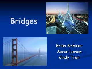
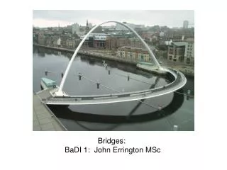
Bridges: BaDI 1: John Errington MSc. King Edward VII bridge and Redheugh bridge. Early bridges.

E N D
Bridges: BaDI 1: John Errington MSc
Early bridges Early beam bridges were made from felled trees, used to span streams. An alternative was to culvert the stream and fill in to make the roadway. Both of these were very temporary and liable to be washed away when the river flooded. In the thirteenth century the first mediaeval bridge was built at Corbridge to span the Tyne river. Unfortunately it became derelict by the sixteenth century and was finally replaced in 1674 by the bridge you can see today.
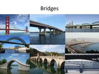
Modern Bridge Designs • There are six basic modern bridge forms: the beam, the truss, the arch, the cantilever, the cable-stay, and the suspension. • A beam bridge is made of long timber, metal, or concrete beams anchored at each end. If the beams are arranged in a lattice, such as a triangle, so that each shares only a portion of the weight on any part of the structure, the result is a truss bridge. An arch bridge has a bowed shape causing the vertical force of the weight it carries to produce a horizontal outward force at its ends. It may be constructed of steel, concrete, or masonry.
Cantilever bridge • A cantilever bridge is formed by self-supporting arms anchored at and projecting toward one another from the ends; they meet in the middle of the span where they are connected together or support a third member. Single-piece, rolled steel beams can support spans of 50 to 100 ft (15–30 m), depending on the load. Larger, built-up beams are made for longer spans; a steel box-beam bridge with an 850-ft (260-m) span crosses the Rhine at Cologne. • The cantilevered Forth Bridge (1890) in Scotland was the first major structure built entirely of steel, the material that made possible its two record-setting spans of 1,710 ft (521 m) each.
Forth Rail bridge Located 9 miles (14 km) west of Edinburgh, the Forth Railway Bridge is a remarkable cantilever structure which is still regarded as an engineering marvel. The bridge was built to carry the two tracks of the North British Railway the 1½ miles (2½ km) over the Firth of Forth between South Queensferry and North Queensferry, at a height of 46m (150 feet) above the high tide. The structure has three massive cantilever towers each 104m (340 feet) high. During its construction each tower was built in balance to prevent excess tension loading on the supports.
Truss Bridges • The truss can span even greater distances and carry heavy loads; it is therefore commonly used for railroad bridges. A large truss span like that over the Columbia River can extend to 1,232 ft (376 m). • If the truss is shaped into an arch, even longer bridges are possible; the Bayonne Bridge between New York and New Jersey, and the Sydney Harbor Bridge in Australia, are the longest steel arch bridges, at 1,675 ft (510 m), and 1,670 ft (509 m) respectively.
Concrete arch bridges • Concrete arch bridges tend to be somewhat smaller than truss bridges, the largest being the Krk Bridge in Croatia and the Gladesville Bridge across the Parramatta River at Sidney, Australia, at 1,280 ft (390 m) and 1,000 ft (305 m), respectively. • Usually arch bridges employ vertical supports called "spandrels" to distribute the weight of the roadway to the arch below
Natchez Trace Bridge The Natchez Trace Parkway Bridge is the nation's first segmentally constructed concrete arch bridge. Spanning 502 m (1,648 feet), the double arch structure offers motorists a view from 47m (155 feet) above the valley floor and is one of the final links in the Natchez Trace Parkway project. The bridge's arches are designed to support the deck without evenly spaced spandrel columns, resulting in a picturesque, unencumbered appearance.
Cable-Stayed Bridges • The cable-stayed bridge is the most modern type, coming into prominence during the 1950s. The longest is the Tatara Bridge in Ehime, Japan. • In a cable-stayed bridge, the roadway is supported by cables attached directly to the supporting tower or towers. This differs from a suspension bridge, where the roadway is suspended from vertical cables that are in turn attached to two or more main cables. These main cables hang from two towers and have their ends anchored in bedrock or concrete.
Tatara Bridge The Tatara Bridge in Japan is a 3-span continuous cable-stayed bridge with a steel box girder deck. With a centre span of 890 m, and a total length of 1,480 m it is the longest cable-stayed bridge in the world.
Suspension Bridges • The suspension bridge is used for the longest spans. • The design of suspension bridges advanced when J. A. Roebling, a German-born engineer designed the Brooklyn Bridge across the East River (completed 1883), which was the world's longest suspension bridge at the time of its construction, having a main span of 1,595.5 ft (487 m). • Today the longest spans in the world are suspended. The longest main spans are the Akashi Kaikyo Bridge, Hyogo, Japan, 6,529 ft (1,990 m); Humber River Bridge, Hull, England, 4,626 ft (1410 m); Golden Gate Bridge, San Francisco, 4,200 ft (1,280 m);
Suspension bridges The Clifton Suspension Bridge, spanning the beautiful Avon Gorge, designed by Isambard Kingdom Brunel who was appointed project engineer. The chains and suspension rods are made of wrought iron. The total length is 1,352 ft (414 m), with a centre span of 702 ft (214 m) Akashi-Kaikyō Ōhashi) is a suspension bridge in Japan that crosses the Akashi Strait as part of the Honshu-Shikoku Highway. The central section is the longest bridge span in the world at 1991 m. The central span was originally only 1990 meters but was stretched by a further meter in the Kobe earthquake on January 17, 1995. You will see the roadway is built on a truss for rigidity.
Combination spans • Combination spans are often used to bridge even longer stretches of water. • The San Francisco–Oakland Bay Bridge, noted for its three long spans, of which two are suspension spans and the third a cantilever, has a total length of 8.25 mi (13.2 km). • The longest combination spans are the twin Lake Ponchartrain Causeways near New Orleans, Louisiana, whose parallel roadways stretch nearly 24 mi (38 km).
San Francisco-Oakland Bay Bridge Western portion viewed from San Francisco showing the four towers of two suspension bridges and their central anchorage Eastern Cantilever Bridge, and truss bridges viewed from Yerba Buena Island at the entrance to the Coast Guard station
In a Deck configuration, traffic travels on top of the main structure; in a Pony configuration, traffic travels between parallel superstructures which are not cross-braced at the top; in a Through configuration, traffic travels through the superstructure (usually a truss) which is cross-braced above and below the traffic. Examples of the three common travel surface configurations
Truss - simple types • A truss is a structure made of many smaller parts. Once constructed of wooden timbers, and later including iron tension members, most truss bridges are built of metal. • The king post truss is the simplest type; when loaded the angled sections are in compression, with the vertical member and deck in tension. • the queen post truss adds a horizontal top chord to achieve a longer span, but the centre panel tends to be less rigid due to its lack of diagonal bracing.
Pratt truss variations • The basic identifying features of a Pratt truss are the diagonal web members which form a V-shape. The center section commonly has crossing diagonal members. Additional counter braces may be used and can make identification more difficult, however the Pratt and its variations are the most common type of all trusses. • Charles H. Parker modified the Pratt truss to create a "camelback" truss having a top chord which does not stay parallel with the bottom chord. This creates a lighter structure without losing strength; there is less dead load at the ends and more strength concentrated in the center. It is somewhat more complicated to build since the web members vary in length from one panel to the next.
The Warren truss is perhaps the most common truss for both simple and continuous trusses. For smaller spans, no vertical members are used lending the structure a simple look. For longer spans vertical members are added providing extra strength Warren trusses are typically used in spans of between 50 -100m. Warren Truss
Howe truss The Howe truss is the opposite of the Pratt truss. The diagonal members face in the opposite direction and handle compressive forces. This makes it very uneconomic design for steel bridges and its use is rarely seen. Patented in 1840 by William Howe, this design was common on early railroads. The three drawings show various levels of detail. The thicker lines represent wood braces; the thinner lines are iron tension rods. Arch bridges may be constructed using a shaped truss as shown here. A tied arch resists spreading (drift) at its bearings by using the deck as a tie piece.
In analysing stresses on a rigid structure we assume that each joint is ‘pinned’ or in other words hinged so that the members are free to rotate but cannot come apart. Any shape with more than three members is able to deform, as shown here. A rectangle or square can be stabilized or made rigid by adding a brace to make one or more triangles. Depending on the forces acting on the frame the brace may be under tension (a tie) or compression (a strut) B B A A D D C C A B C D About space frames
A Simple Truss Load Truss members are pinned together: this means they are free to rotate C B A d1 d2 Support points of the truss
Reaction Forces in a Simple Truss F1 Force Equilibrium Equation F1 = F2 + F3 Moment Equilibrium Equation F2* d1 = F3* d2 d1 d2 F2 F3
Member Forces in a Simple Truss Load C Truss members have tensile or compressive internal forces Compression Compression Blue arrows indicate the action of the joints on the members B A Tension d1 d2
Joint Forces in a Simple Truss F1 C Notice that for each member the forces at each end are shown equal and opposite. The forces in each joint must be in equilibrium for the truss to be in equilibrium FCA FCB White arrows indicate the action of the members on the joints B A FAB d1 d2 F2 F3
Joint Forces in a Simple Truss F1 C A Free Body Diagram is drawn for each joint in the truss. FCB FCA The joints can be isolated and the equilibrium of each joint determined FCA FCB B A FAB FAB F2 F3
Joint Forces in a Simple Truss FCB Joint C F1 A Force Triangle is drawn for each joint in the truss. FCA Joint B Solve the force triangles for the member forces. Joint A FCB F3 FCA F2 FAB FAB
How Do We Determine Tension and Compression in the Members? When you solve for the forces in the joint, the forces must add head-to-tail. This sets the direction of the forces. To find the force magnitudes, measure the forces in the triangle and scale the values as before. Joint A FCA F2 F2 is a known force from finding the truss reactions. Draw F2 to scale as before. FAB Lines of action of the two unknown forces are in the directions of the truss members they represent.
How Do We Determine Tension and Compression in the Members? Set the arrows from the force triangle over the members at the joint you are analyzing. You have compression when the member force pushes on the joint. A You have tension when the member force pulls away from the joint. FCA F2 F2 FAB Joint A
All the triangles are equilateral triangles, the angle between the sides is 60o Sum of moments at A = (1m)*(-400N) + (3m)*(-800N)+(4m)*E = 0 : E=700N Sum of forces = Ay+ E - 400N - 800N: Ay=500N Force analysis of a simple truss
Now that we know how the forces are laid out, lets take a look at what is happening at point A. • Remember that all forces are in equilibrium, so they must add up to zero
Remember the system is in equilibrium, so the forces must all balance out. If there was a net force in any direction something would have to move. Sum of Fx= TAC + TAB cos 60o = 0 Sum of Fy= TAB sin 60o +500N = 0 Solving for the two above equations we get TAB = -577N TAC= 289N
Compression and Tension TAB = -577N TAC = 289N negative force means that there is a compression force, and positive force means that there is a tension force
Sum of Fx = TBD + TBC cos 60o + 577 cos 60o= 0 Sum of Fy = -400N + 577sin60o -TBCsin60o=0 Once again, solving the two equations TBC = 115N TBD = -346N Forces and moments at point B
Tension and Compression TBC = 115N TBD = -346N BD (negative) is under compression, while BC (positive) is under tension
Forces in a Truss If we calculate the rest of the forces acting on the various points of our truss, we will see that there is a mixture of both compression and tension forces and that these forces are spread out across the truss. Remember: negative force means that there is a compression force and a positive force means that there is a tension force TBD= -346N TAB = -577N TBC=115N TAC= 289N
Limitations of a Truss • As the unsupported span increases the weight of the bridge increases, and so its load efficiency falls. • Truss bridges are very heavy due to the massive amount of material involved in construction. • Truss bridges can be built to take advantage of materials that are good under tension (e.g. steel) and under compression (e.g. timber) • Computer packages are available to take the hard work out of bridge calculations.
References • http://www.du.edu/~jcalvert/tech/machines/bridges.htm • http://pghbridges.com/basics.htm • http://www.matsuo-bridge.co.jp/ • http://www.jhu.edu/~virtlab/bridge/truss.htm