Download
1 / 49
490 likes | 645 Vues
Fast Beam Collision Feedbacks for luminosity optimisation at next-generation lepton colliders. Philip Burrows John Adams Institute Oxford University. Outline. Introduction and system concept ILC design status CLIC design status FONT prototype systems performance

E N D
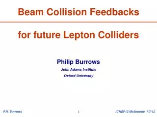
Fast Beam Collision Feedbacks for luminosity optimisation at next-generation lepton colliders Philip Burrows John Adams Institute Oxford University P.N. Burrows EPS13 Stockholm 20/7/13
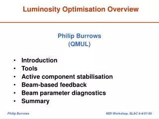
Outline • Introduction and system concept • ILC design status • CLIC design status • FONT prototype systems performance • Outstanding technical issues • Summary P.N. Burrows EPS13 Stockholm 20/7/13
Compact Linear Collider (CLIC) Drive Beam Generation Complex Main Beam Generation Complex 1.5 TeV / beam P.N. Burrows EPS13 Stockholm 20/7/13
International Linear Collider c. 250 GeV / beam 31 km P.N. Burrows EPS13 Stockholm 20/7/13
Beam parameters ILC 500 CLIC 3 TeV P.N. Burrows EPS13 Stockholm 20/7/13
Beam parameters ILC 500 CLIC 3 TeV Electrons/bunch 20.37 10**10 P.N. Burrows EPS13 Stockholm 20/7/13
Beam parameters ILC 500 CLIC 3 TeV Electrons/bunch 20.37 10**10 Bunches/train 1312 312 P.N. Burrows EPS13 Stockholm 20/7/13
Beam parameters ILC 500 CLIC 3 TeV Electrons/bunch 20.37 10**10 Bunches/train 1312 312 Bunch separation 554 0.5 ns P.N. Burrows EPS13 Stockholm 20/7/13
Beam parameters ILC 500 CLIC 3 TeV Electrons/bunch 20.37 10**10 Bunches/train 1312 312 Bunch separation 554 0.5 ns Train length 727 0.156 us P.N. Burrows EPS13 Stockholm 20/7/13
Beam parameters ILC 500 CLIC 3 TeV Electrons/bunch 20.37 10**10 Bunches/train 1312 312 Bunch separation 554 0.5 ns Train length 727 0.156 us Train repetition rate 550 Hz P.N. Burrows EPS13 Stockholm 20/7/13
Beam parameters ILC 500 CLIC 3 TeV Electrons/bunch 20.37 10**10 Bunches/train 1312 312 Bunch separation 554 0.5 ns Train length 727 0.156 us Train repetition rate 550 Hz Horizontal IP beam size 47440 nm Vertical IP beam size 6 1 nm P.N. Burrows EPS13 Stockholm 20/7/13
Beam parameters ILC 500 CLIC 3 TeV Electrons/bunch 20.37 10**10 Bunches/train 1312 312 Bunch separation 554 0.5 ns Train length 727 0.156 us Train repetition rate 550 Hz Horizontal IP beam size 47440 nm Vertical IP beam size 6 1 nm Longitudinal IP beam size 30044 um Luminosity 26 10**34 P.N. Burrows EPS13 Stockholm 20/7/13
Beam parameters ILC 500 1000CLIC 3 TeV Electrons/bunch 220.37 10**10 Bunches/train 1312 2450312 Bunch separation 554 3660.5 ns Train length 727 8970.156 us Train repetition rate 5450 Hz Horizontal IP beam size 47433540 nm Vertical IP beam size 63 1 nm Longitudinal IP beam size 30022444 um Luminosity 256 10**34 P.N. Burrows EPS13 Stockholm 20/7/13
Beam parameters ILC 500 1000CLIC 3 TeV Electrons/bunch 220.37 10**10 Bunches/train 1312 2450312 Bunch separation 554 3660.5 ns Train length 727 8970.156 us Train repetition rate 5450 Hz Horizontal IP beam size 47433540 nm Vertical IP beam size 63 1 nm Longitudinal IP beam size 30022444 um Luminosity 256 10**34 P.N. Burrows EPS13 Stockholm 20/7/13
IP beam feedback concept • Last line of defence against relative beam misalignment • Measure vertical position of outgoing beam and hence beam-beam kick angle • Use fast amplifier and kicker to correct vertical position of beam incoming to IR FONT – Feedback On Nanosecond Timescales P.N. Burrows EPS13 Stockholm 20/7/13
General considerations Time structure of bunch train: ILC (500 GeV): c. 1300 bunches w. c. 500 ns separation CLIC (3 TeV): c. 300 bunches w. c. 0.5 ns separation Feedback latency: ILC: O(100ns) latency budget allows digital approach CLIC: O(10ns) latency requires analogue approach Recall speed of light: c = 30 cm / ns: FB hardware should be close to IP (especially for CLIC!) Two systems, one on each side of IP, allow for redundancy P.N. Burrows EPS13 Stockholm 20/7/13
IP FB Design Status: ILC Engineering design documented in ILC TDR (2013): 1.IP beam position feedback: beam position correction up to +- 300 nm vertical at IP 2. IP beam angle feedback: hardware located few 100 metres upstream conceptually very similar to position FB, less critical 3. Bunch-by-bunch luminosity signal (from ‘BEAMCAL’) ‘special’ systems requiring dedicated hardware + data links P.N. Burrows EPS13 Stockholm 20/7/13
Door Cavern wall SiD ILC IR: SiD for illustration P.N. Burrows EPS13 Stockholm 20/7/13
Door Cavern wall SiD ILC IR: SiD for illustration P.N. Burrows EPS13 Stockholm 20/7/13
Final Doublet Region (SiD) P.N. Burrows EPS13 Stockholm 20/7/13
Final Doublet Region (SiD) P.N. Burrows EPS13 Stockholm 20/7/13
QD0 – QF1 Region (SiD) P.N. Burrows EPS13 Stockholm 20/7/13
QD0 – QF1 Region (SiD) P.N. Burrows EPS13 Stockholm 20/7/13
Final Doublet Region (SiD) P.N. Burrows EPS13 Stockholm 20/7/13
ILC FB prototype: FONT at KEK/ATF Kicker BPM 1 BPM 2 BPM 3 e- Drive amplifier Analogue BPM processor Digital feedback P.N. Burrows EPS13 Stockholm 20/7/13
ILC prototype: FONT4 at KEK/ATF Kicker BPM 1 BPM 2 BPM 3 e- Drive amplifier Analogue BPM processor Digital feedback P.N. Burrows EPS13 Stockholm 20/7/13
ILC prototype: FONT4 at KEK/ATF Kicker BPM 1 BPM 2 BPM 3 e- Drive amplifier Analogue BPM processor Digital feedback BPM resolution < 0.5um Latency ~ 130ns Drive power > 300nm @ ILC P.N. Burrows EPS13 Stockholm 20/7/13
Latency P.N. Burrows EPS13 Stockholm 20/7/13
ILC IP FB performance Resta Lopez P.N. Burrows EPS13 Stockholm 20/7/13
IP FB Design Status: CLIC Conceptual design developed and documented in CLIC CDR (2012) NB primary method for control of beam collision overlap is via vibration isolation of the FF magnets, and dynamic correction of residual component motions IP position feedback: beam position correction up to +- 50 nm vertical at IP More realistic engineering design can be developed in next project phase P.N. Burrows EPS13 Stockholm 20/7/13
CLIC Final Doublet Region P.N. Burrows EPS13 Stockholm 20/7/13
CLIC Final Doublet Region P.N. Burrows EPS13 Stockholm 20/7/13
CLIC Final Doublet Region P.N. Burrows EPS13 Stockholm 20/7/13
CLIC prototype: FONT3 at KEK/ATF Kicker BPM 1 BPM 2 BPM 3 e- Analogue BPM processor P.N. Burrows EPS13 Stockholm 20/7/13
CLIC prototype: FONT3 at KEK/ATF Kicker BPM 1 BPM 2 BPM 3 e- Analogue BPM processor Electronics latency ~ 13ns Drive power > 50nm @ CLIC P.N. Burrows EPS13 Stockholm 20/7/13
CLIC IP FB performance Single random seed of GM C Resta Lopez P.N. Burrows EPS13 Stockholm 20/7/13
CLIC IP FB performance For noisy sites: factor 2 - 3 improvement P.N. Burrows EPS13 Stockholm 20/7/13
Outstanding Technical Issues • Component designs need to be optimised for tight spatial environments • Routing of cables • Operation of (ferrite) devices in large, spatially-varying B-field • Further studies of radiation environment • Electronics location, rad hardness, shielding • RF interference: beam FB electronics • kicker detector P.N. Burrows EPS13 Stockholm 20/7/13
Summary • Well developed IP collision FB system designs for both ILC and CLIC • Simulations demonstrate luminosity recovery capability • Demonstrated prototypes with required performance parameters • Progress on designing customised beamline components + optimising layout • Ideas applicable at XFELs + rings P.N. Burrows EPS13 Stockholm 20/7/13
NEWSFLASH from ATF2 • Beam size ~ 65 nm achieved • First attempts at stabilisation of small beam at nm level P.N. Burrows EPS13 Stockholm 20/7/13
Layout with new IP kicker Designed by Oxford Fabrication arranged by KEK Installed May 2012
ATF2 IPFB tests June 2013 IP kicker Cavity IPBPM e- FONT amplifier IPBPM electronics FONT digital FB
ATF2 IP FB results (June 2013) Bunch 1: Not corrected by FB Incoming position jitter ~ 200nm
ATF2 IP FB results (June 2013) Bunch 1: Not corrected by FB Incoming position jitter ~ 200nm Bunch 2: FB off jitter ~ 200nm FB on: beam zeroed jitter reduced ~ 100nm PRELIMINARY