Download
1 / 5
60 likes | 274 Vues
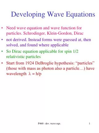
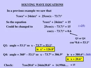
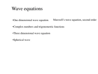
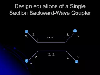
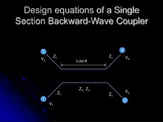
Design equations of a Single Section Backward-Wave Coupler. 4. 3. Z c. Z c. V 4. V 3. l= λ o/4. Z e,. Z o. V 2. Z c. Z c. 1. 2. V 1. Specify : Midband Operating frequency : f o Port Impedances : Z c Mean coupling in dB : -20 log 10 C v Coupler Parameters:

E N D
Design equations of a Single Section Backward-Wave Coupler 4 3 Zc Zc V4 V3 l=λo/4 Ze, Zo V2 Zc Zc 1 2 V1
Specify: Midband Operating frequency : fo Port Impedances : Zc Mean coupling in dB : -20 log10Cv Coupler Parameters: Coupling Length l=λo/4 (λo : guide wavelength at fo) Ze= Zc ((1+Cv)/(1-Cv))1/2 , Zo = Zc ((1-Cv)/(1+Cv)) Frequency Response: IV3/V2I2 = Cv2sin2θ/(1-Cv2sin2 θ) ; θ= (Π/2).( λo/ λ) IV2/V1I2 = Cv2sin2θ/(1-Cv2sin2 θ) Couplingin dB = -20 log10IV3/V1I
PARALLEL COUPLED DIRECTIONAL COUPLERSingle section Backward wave coupler • Offer much larger BWs as compared with the Branch Line coupler • Mostly backward wave couplers although forward wave couplers are also possible with the case of INHOMOGENOUS medium • Most commonly used Parallel coupled DC is the TEM mode single section Backward wave coupler. • The term BACKWARD wave coupler implies the ELECTRIC and MAGNETIC FIELD interaction between the parallel coupled conductors causes the coupled signal to travel in the direction opposite to that of the INPUT SIGNAL. • Maximum coupling occurs when the length of the coupling region is equal to ONE QUARTER wavelength in propagating medium
EDGESIDE COUPLED STRIPLINE Coupled Power P3=P1-P2 Isolated Port P4 Plane of symmetry 3 4 εo εr w s w 2 Θ (L=λo/4) 1 Output Power P2 Input Power P1
BROADSIDE COUPLED STRIPLINE Isolated Port P4 Coupled Power P3=P1-P2 4 3 Plane of symmetry εo εr w1 w Θ (L=λo/4) 1 2 Input Power P1 Output Power P2