Download
1 / 7
80 likes | 256 Vues
Airflow Impedance, Fan Configuration, and Heat Sink Design. ME 114 Lab 4. Airflow Impedance. Impedance: obstruction to movement (in this case, airflow) For a given pressure head, increasing the impedance causes airflow to drop.

E N D
Airflow Impedance, Fan Configuration, and Heat Sink Design ME 114 Lab 4
Airflow Impedance • Impedance: obstruction to movement (in this case, airflow) • For a given pressure head, increasing the impedance causes airflow to drop. • Alternately, if a certain rate of airflow is needed, a larger pressure head must be overcome if the impedance is greater.
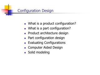
Series vs. Parallel Fan Configurations • To compensate for the system impedance, fans can be used either alone, in series, or in parallel. • Parallel fans double the flowrate for a given impedance. • Series fans double the amount of system impedance fans can overcome for a given flowrate. • For cooling a computer chassis, which configuration would typically be better?
Fan Curves • Fans operate at the intersection of the fan curve and the system impedance curve. Fan and system impedance curves for series configuration. “Series Open” represents the impedance with the chassis doors completely open whereas “Series Closed” represents the impedance with the chassis doors completely closed.
Electronics Cooling Terminology • Chip junction temperature: temperature of the top surface of the chip, where the circuitry is located. This location is not easily accessible to measure. The junction is located inside of the chip case. If this temperature becomes too high, failure rates skyrocket (most electronics have a max junction temperature in the 60-120˚C range). • Case temperature: temperature of the plastic or ceramic case that the chip is embedded in. We can measure this.
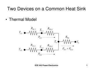
A simple resistance network From Cengel, Heat Transfer: A Practical Approach, 2nd edition, McGraw-Hill.
Tambient Θca Tcase Θjc Tjunction Θjb Tb Θba Tambient Resistance Network for Our Lab In our lab, we’re passing current through a power resistor as our heat source instead of using a chip. This lets us measure Tjunction.